HSM series
1 /58Pages

HSM series
1 /58Pages
Catalog excerpts

Sumitomo DriveTechnologies
Open the catalog to page 1
have made every effort to present concise manner. We hope you will find the format to be satisfactory, enabling you to quickly locate any required information. However if you improvements we would be very pleased to receive them via our SUMITOMO CYCLO EUROPE. Copyright Sumitomo Cyclo Europe Reproduction in part or whole is not permitted without our prior approval. Whilst every care has been taken in preparation of this catalogue, no GENERAL INFORMATION Harsh Environment Sealing
Open the catalog to page 3
Product Features range of shaft mounted speed reducers. In general the gearbox is designed to be mounted directly on the machine shaft of a torque arm or flange thus eliminating the need for a coupling or chain drive. Along with the ratios available a wide selection of output speeds are achievable with the use of a belt drive to the input Alternatively the gearbox can be driven directly from a hydraulic or electric motor using an input flange adapter. The new design incorporates many features as standard that were previously available as options. This new generation of gearboxes is available...
Open the catalog to page 4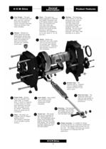
Product Features Case Design - The gear case is manufactured from grey cast iron, precision ensure accurate assembly. There are thirteen case sizes available. metal reinforced double lipped gaiter spring type harsh environments. world wide. helical designed to DIN/ISO a 25 degree pressure angle. from alloy steel, gas shaved and honed (profile machined from alloy steels on journals, gear seating available world wide. designed with roller shaft deep groove ball bearings, with taper roller Output hubs - Output hubs are available with Taper Grip" or parallel bore, in metric or imperial. A wide choice...
Open the catalog to page 5
The HSM can be secured to the driven shaft by means of the Taper-Grip bush which will transmit the torque and shock overload capacity of the selected The Taper-Grip* bush is a unique shaft locking system that overcomes the difficulties which can be experienced with other methods of securing The Taper-Grip® bush allows for easy assembly and disassembly of the shaft mounted speed keyway it avoids any type of The principle of using tapers to secure power transmission components has been established for many years and the Taper-Grip bush system is based on well known locking capabilities of conventional...
Open the catalog to page 6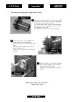
Using the® The ease of using the Taper-Grip® Bush The only tools required for fitting the HSM gearbox with Taper-Grip bush to the application is an alien key and torque wrench. The driven shaft needs to be in good condition, but no lubrication is necessary for the fitting of The shaft must be free of any oil or grease. The bush is fitted to the HSM before being offered to the application. It can then be slid on to the shaft with The Taper-Grip bush can be used on existing keyed shafts. There is no need to cover the existing Once the HSM is in position, the alien key is used to tighten the cap...
Open the catalog to page 7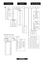
H Customer Unit Size 1 - The Americas 015 4 - Australia / NZ Parallel 107 3 - Africa / Middle East Output Bore 103 2 - Europe Metric 115 eg 050 - 50mm 5 - Japan / S.E. Asia 203 120 - 120mm 6 - Others 207 AGMA & BS 215 7 - Canada eg 103 - 1 3/16 307 Input Shaft Position 315 Taper-Grip® Bush 407 Y - Horizontal 415 A - Vertical Above 507 B - Vertical Below 608 000 - see table for Taper-Grip® Bush code S - Special Order Ratio 05 - 5 : 1 13 - 13 : 1 20 - 20 : 1 25 - 25 : 1 Special Order (For Internal Use Only) Output Bearing D - Deep Groove T - Taper Roller 1 Issue 1 - Metric 0 - Inch Bore Type 012...
Open the catalog to page 10
Gearbox Selection Procedure From page 10 locate the application type and, from the daily operational hours required, select the load classification (I, II From page 10 locate the application type and, from the daily operational hours required, select the load classification (I, II or III). Using the table on page 10, read the service factor (fn1) associated with the load classification. Refer to Class I, II or III selection tables on pages 11 through to 13. From the motor power and output speed required, select the unit size and ratio. Multiply the absorbed power (P1) (or motor power if absorbed...
Open the catalog to page 11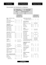
Load Classification Service Factors Recommended Load Classification by Application BRICK, CONCRETE STONE, UNIFORMLY LOADED CONVEYORS - HEAVY DUTY Cutter head gears H FOOD AND SUGAR INDUSTRY Sugar crushing mills M Sugar beet cutter M Sugar cane mills M METAL WORKING MACHINES Machine tools PAPER INDUSTRY Machine glazing cylinders R Centrifugal pumps Plunger pumps ROLLING MILLS Tube straightening machines R Continuous casting machinesR Roller adjustment drives M TEXTILE INDUSTRY WATER TREATMENT
Open the catalog to page 12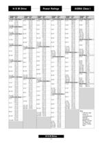
Power Ratings
Open the catalog to page 13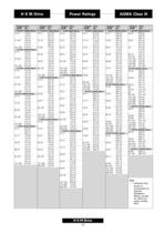
Power Ratings
Open the catalog to page 15
Power Ratings Power Ratings [kW] 5:1 units (Single Reduction) I I Indicates power ratings are governed by thermal limitations. Please consult for effect on using cooling fans.
Open the catalog to page 16
Power Ratings Power Ratings [kW] 13:1, 20:1 and 25:1 units (Double Reduction) I I Indicates power ratings are governed by thermal limitations. Please consult for effect on using cooling fans. I I Indicates the limit of recommended output speed for 20:1 and 25 :1 reducers
Open the catalog to page 17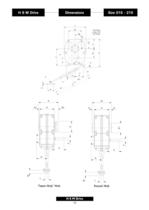
T AA J W CC U BB V HH Holes JJ dia x KK full thread Y 90 X K P K Q R2 O S R1 N A H G2 G H G F F E1 E G1 A1 C C D M D M L 18 L
Open the catalog to page 20
Note: 1). Dimension D is increased by 7mm when a backstop is fitted.
Open the catalog to page 21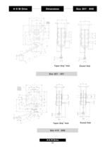
T A AA A1 HH Holes JJ Dia x KK full thread 1 G1 H G2 G G GG2 E J B W U B V H E1 GG F F Y 90 X C Q C P K D K D R2 S M N L AA G1 AA A H G G2 H G BB U W AA F F J FF AA Y BB BB K Q K 90 X P M M R C D O C D L N R L S 20 E B E1 DD EE CC V BB L A1 T HH Holes JJ dia x KK full thread both sides M O R1
Open the catalog to page 22
Note: Dimension D is increased by 7mm when a backstop is fitted. (Sizes 307, 315 & 407)
Open the catalog to page 23
Output Bores Taper Grip (inch) Notes: Taper Grip tolerances up to hi 1 can be accommodated. Hub codes relate to the output hub spare part number (see pages 47 & 49) Other bores available on special order.
Open the catalog to page 24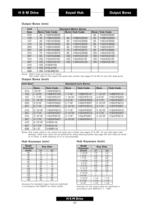
Output Bores Metric hubs are bored to F7 limits. Hub codes relate to the output hub spare part number (see pages 47 & 49) for use with deep grove Output Bores (inch) Notes: Hub codes relate to the output hub spare part number (see pages 47 & 49) for use with taper roller bearings. Other bore types can be achieved by using reducing bushes (see page 24) Inch hubs are bored to h7 limits. A shaft tolerance of h7 is recommended. Keyways for standard output hubs are machined in accordance with BS425 for metric shafts Keyways for the output hubs are machined in accordance with ANSI B17.1 - 1967
Open the catalog to page 25All SUMITOMO (SHI) Cyclo Drive Germany GmbH catalogs and technical brochures
 Paramax 9000 series
281 Pages
 Helical Shaft Mount (HSM)
58 Pages
 Bevel Buddybox 4
60 Pages
 SERVO 6000
38 Pages
 Motion Control DrivesE CYCLO
28 Pages
 BEVEL BUDDYBOX 4
248 Pages
 Cyclo® BBB5
270 Pages
 Fine Cyclo®
123 Pages
 PARAMAX ® 9000 Series
281 Pages
 Fine Cyclo UA Brochure
2 Pages
 Fine Cyclo Flyer
2 Pages
 Precision Drives Product Catalog
20 Pages
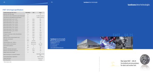 Fine Cyclo F4CF – UA 25
2 Pages
 Fine Cyclo F4CFS–UA 115
4 Pages
 Fine Cyclo F4C–C 25
4 Pages
 Paramax 9000
352 Pages
 Neo Hyponic
120 Pages
 Servo 100
58 Pages
 IB Series catalogues
94 Pages
 Servo 6000 series
6 Pages
 Cyclo® Drive 6000
139 Pages
 Paramax® 9000
352 Pages
 Astero series
186 Pages
 Servo Planetary Gears EPG
6 Pages
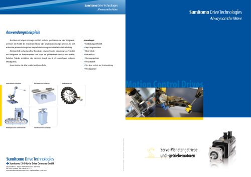 Servo-Planetary Gears
4 Pages
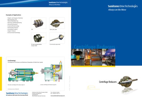 Centrifuge reducers
2 Pages
 Fine Cyclo®
114 Pages


Archived catalogs
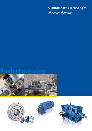 Product overview
16 Pages
- Actuator
- Electric gearmotor
- Electric actuator
- Planetary gearbox
- Coaxial gearhead
- Precision gearhead
- Direct current gear-motor
- Right angle gearhead
- Compact gearhead
- Solid-shaft gearhead
- Gear train gear reducer
- Hollow-shaft gearhead
- Gearbox for industrial applications
- Transmission gearhead
- Right angle electric gearmotor
- Industrial electric gearmotor
- Multi-stage gearhead
- Shaft gearhead
- Single-stage gearhead
- Coaxial gearmotor