- Catalogs
- SUMITOMO (SHI) Cyclo Drive Germany GmbH
- Cyclo® Drive 6000
Cyclo® Drive 6000

Cyclo® Drive 6000
Catalog excerpts

Sumitomo DriveTechnologies Gearmotors & Speed Reducers Getriebemotoren & Getriebe
Open the catalog to page 1
Reproduction in part or whole is not permitted without our prior approval. Whilst every care has been taken in preparation of this catalogue, no liability can be accepted for any errors or omissions. Modifications reserved. Nachdruck, auch auszugsweise, nur mit unserer Genehmigung gestattet. Die Angaben in diesem Katalog wurden mit größter Sorgfalt auf ihre Richtigkeit überprüft. Trotzdem kann für eventuell fehlerhafte oder unvollständige Angaben keine Haftung übernommen werden. Änderungen behalten wir uns vor.
Open the catalog to page 2
CYCLO Drive 6000 Product Information . 3 CYCLO Drive 6000 Produktinformation .. 3 Typenbezeichnung CYCLO Drive 6000 .10 BUREAU VERITAS
Open the catalog to page 3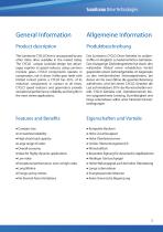
Sumitomo DriveTechnologies General Information Product description The Sumitomo CYCLO Drive is unsurpassed by any other inline drive available in the market today. The CYCLO unique cycloidal design has advan- tages superior to speed reducers using common involute gears. CYCLO components operate in compression, not in shear. Unlike gear teeth with limited contact points, a CYCLO has 30% of its reduction components in contact at all times. CYCLO speed reducers and gearmotors provide exceptional performance, reliability and long life in the most severe applications. Allgemeine Information Das Sumitomo...
Open the catalog to page 4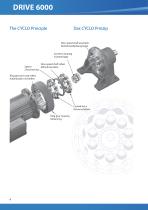
The CYCLO Principle Das CYCLO Prinzip Slow speed shaft assembly Eccentric bearing Slow speed shaft rollers Spacer Mitnehmerrollen Ring gear pins and rollers
Open the catalog to page 5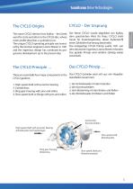
Sumitomo DriveTechnologies The name CYCLO derives from Kyklos - the Greek word for circle and refers to the CYCLO disc, whose outer profile describes a cycloidal curve. The unique CYCLO operating principle was invent- ed by the German engineer Lorenz Braren in 1931 and the ingenious design has continued its pro- gressive development up to the present day. Der Name CYCLO wurde abgeleitet von Kyklos, dem griechischen Wort fur Kreis. CYCLO steht heute fur Exzentergetriebe, deren AuBenprofil einen Zykloiden-Kurvenzug beschreibt. Das einzigartige CYCLO Prinzip wurde 1931 von dem deutschen Ingenieur...
Open the catalog to page 6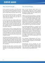
As the eccentric cam rotates, it rolls the cycloid discs around the internal circumference of the sta- tionary ring gear. The resulting action is similar to that of a wheel rolling around the inside of a ring. As the wheel (cycloid disc) travels in a clockwise path around the ring (ring gear housing), the wheel itself turns slowly on its own axis in a counter-clockwise direction. In the CYCLO system the cycloidal profile around the outer edge of the disc engages progressively with the rollers of the fixed ring gear housing to produce a reverse rotation at reduced speed. For each complete revolution...
Open the catalog to page 7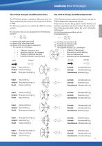
Sumitomo DriveTechnologies The CYCLO Principle als differential drive Das CYCLO Prinzip als Differentialantrieb The CYCLO Gear design is suitable as differential drive, the three components input, output and casing can be driven The following equations are valid for the different moving The reduction ratio can be calculated from the following n-|=speed of the high speed shaft n2=speed of the slow speed shaft n3=speed of the casing (special application "Effective" reduction ratio Reduction ratio acc. to catalogue Change of rotational direction Rotational direction same as input Input: Input shaft...
Open the catalog to page 8
• Extreme Shock Overload Capacity Since the CYCLO system distributes the load to numerous cycloid teeth, it can withstand extreme momentary inter- mittent shock overloads in emergency situations. At least 30 % of the CYCLO's unique disc profiles share the shock overload and the components are in compression - • Compact Size Reduction ratios from 3:1 to 119:1 are available for single stage units and for example, triple stages units offer ratios • Overall Economy Competitive initial cost, high reliability, long life and minimum of maintenance give CYCLO gearmotor superior over- all economy when...
Open the catalog to page 9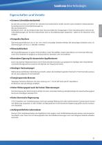
Sumitomo DriveTechnologies • Extreme Schockiiberlastbarkeit Da sich die Last stets auf mehrere der robusten Kurvenabschnitte verteilt, lasst ein Cyclo Getriebe in Notsituationen kurzzeitig extreme Schockuberlastungen zu. Mindestens 30% der Kurvenabschnitte einer Kurvenscheibe des einzigartigen CYCLO Getriebesystems nehmen die Schockbelastungen auf. Die Kurvenabschnitte sind nur Druckbelastungen ausgesetzt - daher ist ein Abscheren nicht • Kompakte Bauform Ubersetzungsverhaltnisse von 3:1 bis 119:1 sind fur einstufige Getriebe lieferbar. Bei dreistufigen Getrieben sind z. B. Mit Anschaffungskosten...
Open the catalog to page 10
11 Sumitomo Drive Technologies
Open the catalog to page 12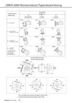
Shaft position Foot mounting vertical down vertikal nach unten vertikal nach oben The standard terminal box position is N33- N3A Sumitomo Drive Technologies 12
Open the catalog to page 13
13 Sumitomo Drive Technologies
Open the catalog to page 14
DRIVE 6000 Gear motor selection 1. Select correct service factor 1. Wählen Sie den richtigen Betriebsfaktor The ratings shown in the selection tables are based on a running time of 10 hours per day with uniform load, including up to 10 starts or stops per hour, at which the momentary peak torque is up to 200 % of the rated torque. If actual working conditions are different, then an equivalent service factor fB1 must be selected from table for load classification by application or ratio of inertia together with table for service factor. Die Daten in den Auswahllisten für Getriebemotoren beziehen...
Open the catalog to page 15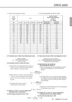
3. Check thermal capacity of motor 3. Erwarmungskapazitat des Motors prufen without brake with brake ohne Bremse 4.1) Calculate value C-Wert from following Formula: 4.1) Berechnen Sie den C-Wert nach folgender Formel: total inertia except motor 4.2) Calculate number of starts per hour Z a) Assume that one operating period consists of motor is started nr times per cycle. b) When inching, nj [times cycle] is included in 1 cycle (ta -K^) the number of inching times per hour Zj is then included in the number c) Calculate total number of Starts Q _ Gesamttraqheitsmoment ohne Motor a) Wenn nr die Anzahl...
Open the catalog to page 16All SUMITOMO (SHI) Cyclo Drive Germany GmbH catalogs and technical brochures
 Paramax 9000 series
281 Pages
 Helical Shaft Mount (HSM)
58 Pages
 Bevel Buddybox 4
60 Pages
 SERVO 6000
38 Pages
 Motion Control DrivesE CYCLO
28 Pages
 BEVEL BUDDYBOX 4
248 Pages
 Cyclo® BBB5
270 Pages
 Fine Cyclo®
123 Pages
 PARAMAX ® 9000 Series
281 Pages
 Fine Cyclo UA Brochure
2 Pages
 Fine Cyclo Flyer
2 Pages
 Precision Drives Product Catalog
20 Pages
 Fine Cyclo F4CF – UA 25
2 Pages
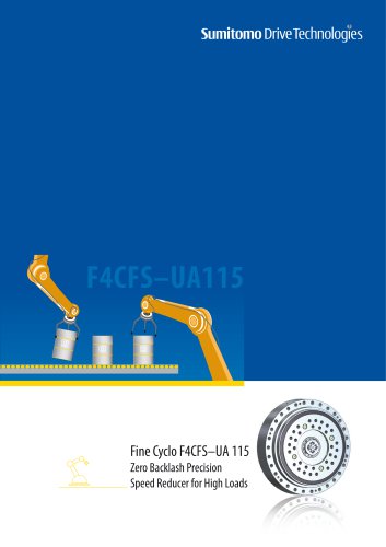 Fine Cyclo F4CFS–UA 115
4 Pages
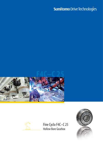 Fine Cyclo F4C–C 25
4 Pages
 Paramax 9000
352 Pages
 Neo Hyponic
120 Pages
 Servo 100
58 Pages
 IB Series catalogues
94 Pages
 Servo 6000 series
6 Pages
 Paramax® 9000
352 Pages
 HSM series
58 Pages
 Astero series
186 Pages
 Servo Planetary Gears EPG
6 Pages
 Servo-Planetary Gears
4 Pages
 Centrifuge reducers
2 Pages
 Fine Cyclo®
114 Pages


Archived catalogs
 Product overview
16 Pages
- Actuator
- Electric gearmotor
- Electric actuator
- Planetary gearbox
- Coaxial gearhead
- Precision gearhead
- Direct current gear-motor
- Right angle gearhead
- Compact gearhead
- Solid-shaft gearhead
- Gear train gear reducer
- Hollow-shaft gearhead
- Gearbox for industrial applications
- Transmission gearhead
- Right angle electric gearmotor
- Industrial electric gearmotor
- Multi-stage gearhead
- Shaft gearhead
- Single-stage gearhead
- Coaxial gearmotor