
- Catalogs
- SUMITOMO (SHI) Cyclo Drive Germany GmbH
- Bevel Buddybox 4

Bevel Buddybox 4
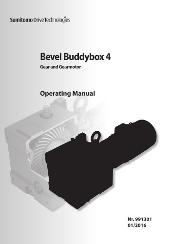
Bevel Buddybox 4
- Adhere to safety notes to prevent injury or damage.
- Use only original spare parts to maintain warranty.
- Installation and maintenance should be performed by qualified professionals, especially in ATEX areas.
- Check for transport damage immediately upon receipt.
- Verify model number matches the purchase order.
- Ensure all bolts and nuts are tightened.
- Verify product information such as type prefix, motor power, and mounting style matches order specifications.
- Store in a stable location and handle properly to avoid damage.
- Follow specific precautions for installation, especially in ATEX areas.
- Ensure proper ventilation and avoid external heat sources.
- Units are shipped without oil; fill with the correct lubricant before operation.
- Refer to the manual for detailed lubrication procedures and intervals.
- Ensure electrical installation is performed correctly to avoid hazards.
- Check brake motors for wear and ensure motor protection is in place.
- Follow the troubleshooting guide for issues with the reducer or motor.
The shrink disc bore should be H8. For high shock loading or large radial loads, a shaft tolerance of js6 or k6 is recommended.
A table provides bolt sizes and corresponding torque values for different models of shrink discs. For example, the TAS-3071-55x68 model requires 10 x M6x25 bolts with a torque of 12 N•m.
Align the driven shaft with the bore of the reducer/gearmotor and slide the unit onto the shaft. Use a mallet if the fit is tight, but avoid damaging the housing or seals. Do not use grease or oil on the driven shaft or bore of the shrink disc to ensure proper torque transmission.
For a 3-piece design shrink disc, tighten bolts uniformly in a clockwise pattern, ensuring both plates remain parallel. Tighten bolts by 30 degrees each time until the specified torque is reached.
The torque arm prevents counter-rotation of the shaft-mounted reducer/gearmotor. It must be mounted in tension, especially if the mounting point is more than 150mm from the machine. Detailed steps are provided for installing a turnbuckle type torque arm.
Outlines the removal process for the BBB4 unit with different types of bushings, emphasizing ensuring electrical power is locked out before starting the removal process.
The Taconite Seal system uses a grease purging system to prevent contaminants. Guidelines for maintaining lubrication are provided, including adding grease according to specified cycles and ensuring seals are not over-tightened.
Details lubrication requirements for the BBB4 series built for the Y4 mounting configuration. The Cyclo and bevel gear portions must be filled and maintained separately.
The unit's model nameplate provides information on unit size, reduction ratio, and mounting configuration. Lubrication methods are determined using Tables 15 and 16.
Table 15 outlines lubrication methods for configurations Y1, Y2, Y3, Y5, and Y6, while Table 16 specifies methods for Y4 configuration. The Cyclo portion is maintenance-free grease lubricated, and the bevel gear portion uses oil.
Table 17 lists recommended oils for the bevel gear and Cyclo portions, with specific oils from manufacturers like AVIA, MOBIL, and SHELL. Table 18 provides recommended oil viscosity based on operating temperatures.
Tables 20 and 21 provide approximate oil quantities for single and double reduction units. Check oil levels every 5,000 hours and change oil every 10,000 hours or 2 years.
Detailed steps for oil filling and draining are provided, including safety precautions and the importance of consulting with Sumitomo for gearmotor overhauls.
Tables 22 and 23 list grease quantities for single and double reduction units. Procedures for grease replenishment and replacement are outlined, emphasizing not to exceed specified quantities to avoid damage.
Installation and maintenance must be performed by qualified personnel, adhering to safety standards like DIN VDE 0105. Motors are sealed, air-cooled, and comply with the Low Voltage Directive 2014/35/EG.
When connecting motors via brackets or an IEC flange, an IP65 seal must be provided by the customer. Ensure ventilation openings in the fan hood are not blocked, and maintain a minimum distance between the hood and the wall for adequate cooling.
Standard and brake motors have specified FB and FA measurements depending on motor size.
Conduit threat sizes vary by frame size. Cable glands must meet the motor protection class, and unused glands should be closed.
Brake motors are connected according to specific circuit diagrams, with brake control voltage noted on the rating plate. For motors driven by an inverter, the brake must be supplied separately.
Brake torque, reaction time, motor inertia, and brake energy are detailed for various motor types and power ratings.
Regular checks for brake wear are necessary, with specific air gap limits provided for different brake types.
When operating motors on a frequency converter, observe the converter manufacturer’s EMC notes and take appropriate suppression measures.
Motor protection switches must be set according to the current value on the rating plate. Thermo contacts and cold conductors should be used to prevent overheating.
External fans have separate terminal boxes with specific voltage and wiring information.
Ensure all safety instructions are followed, and the installation complies with regulations. Check that all connections are secure and that the motor runs quietly without load before attaching it to the driven machine.
Detailed part numbers and descriptions are provided for BBB4 Reducer and Cyclo Planetary Reduction components.
Catalog excerpts

Bevel Buddybox 4 Gear and Gearmotor Operating Manual
Open the catalog to page 1
Table of Contents Important Notes . . . . . . . . . . . . . . . . . . . . . . . . . . . . . . 2 General Notes . . . . . . . . . . . . . . . . . . . . . . . . . 2 Spare parts . . . . . . . . . . . . . . . . . . . . . . . . . . . 2 Important Notes . . . . . . . . . . . . . . . . . . . . . . . . . . . . . . 3 Safety notes . . . . . . . . . . . . . . . . . . . . . . . . . . 3 Safety instructions for use in an ATEX area . . . . . . . 3 Notes on transport . . . . . . . . . . . . . . . . . . . . . . 3 Important Notes . . . . . . . . . . . . . . . . . . . . . . . . . . . . . . 4 Inspection Upon Delivery...
Open the catalog to page 2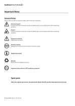
Important Notes General Notes Please make sure that you heed the safety notes in this documentation. Electrical hazards Using the machine incorrectly may lead to bodily injury, serious injuries and/or life-threatening situations. Hazard Using the machine incorrectly may lead to bodily injury, serious injuries and/or life-threatening situations. Dangerous situation Slight injury may result. Harmful situation Damage to the drive or the environment could be caused. Helpful information Disposal Please obey the regulations in force. Important information on ATEX explosion protection Spare parts Only...
Open the catalog to page 3
Important Notes Safety notes Before working on the machine (assembling, operating, maintaining, inspecting etc.), please read these operating instructions through carefully so that you know exactly how to operate the gearbox properly, you know the safety regulations to be applied and the warnings to be heeded. Keep these instructions near by the machine so that you can refer to them at any time if necessary. Transport, installation, lubrication, operation, maintenance and inspections should only be carried out by properly trained technicians, otherwise injury or damage to the machine may result....
Open the catalog to page 4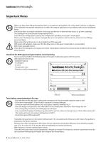
Important Notes Make sure that when fitting the gearbox there is no explosive atmosphere, oils, acids, gases, vapours or radiation. Check whether the ambient temperature is within the range of application in accordance with section Installation Notes. Ensure that there is enough ventilation to the gear and there is no external heat source (e. g. from couplings). The cooling air must not exceed a temperature of 40°C. Check that the configuration matches the configuration specified on the gear's model plate. Please note: The design may only be changed after prior consultation with Sumitomo, otherwise...
Open the catalog to page 5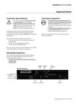
Important Notes Inspection Upon Delivery Lubrication Inspection • In order to avoid injury, ensure that the unit is in a stable position before unpacking. • Verify that the unit received matches your order. Using the incorrect product may cause equipment damage or personal injury. • Do not remove the nameplate from the unit. Upon delivery, inspect the unit for damage that may have occurred during shipment. Notify the shipping company immediately if you find any damage. Do not install or operate a damaged unit. • Oil lubricated units are shipped without oil, unless the customer specified otherwise...
Open the catalog to page 6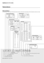
Nomenclature Nomenclature Our nomenclature details specific information about our products. Verify that the nomenclature of the unit delivered matches your order. Mounting Style Output Shaft Orientation Type Horizontal Vertical Vertical Up (Solid Shaft) Type Shaft Mount (Hollow Shaft) Flange (Solid Shaft) Foot (Solid Shaft) Input Connection Type of Input Gearmotor Free Input Shaft w/ Input Adaptor w/Quill Adaptor Reducer Gearmotor Prefix Prefix M J X Modification Type Unit built with special mods Shrink Disc No special mods applied Motor Power (applies only to 1450 RPM) Motor Power Frame Size...
Open the catalog to page 7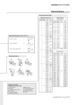
Nomenclature, continued Nominal and Exact Ratio Output Shaft Direction (shafted model only) Projects to Left Side Projects to Right Side Projects to Both Left/Right Sides Mounting Positions Nomenclature Example: LHYMS-6-4A125-EY1-B-28 L - Bevel Buddybox H - Horizontal Y - Shaft Mount (Hollow Shaft) M - Gearmotor S - Special Modifications 6 - 4 kW Motor, 1450 RPM 4A125 - Frame Size E - Metric Shaft Specification Y1 - Mounting Position B - Brake (gearmotor only) 28 - Ratio Frame Size Frame Size
Open the catalog to page 8
Storing and Transporting Storage Location • Store the unit in a clean, dry area. • Do not store outdoors or in an area with high humidity, dust, sudden temperature changes, or corrosive gases. Generally, the BBB4 gearbox is to be stored indoors, in an ordinary factory or a warehouse. The unit should be sealed, wrapped in plastic and additionally packed with desiccant. Desiccant should be replaced periodically to keep the inside of the box dry. Use of color changing desiccant will aid in identifying when desiccant should be changed. Storage Period • Do not store the unit for longer than 3 months...
Open the catalog to page 9
Installation Notes Installation Precautions • Do not use the reducer/gearmotor for specifications other than those shown on the nameplate or in the manufacturing specification documents. Personal injury and/or equipment damage may occur. • Do not place combustible material on or around the unit; fire may occur. • Do not place any objects around the unit that will prohibit proper ventilation. Inadequate ventilation may lead to high unit temperature and/or fire. • Do not step on or hang from the unit. Excessive weight may cause component breakage leading to personal injury and/or equipment damage....
Open the catalog to page 10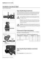
Installation onto Driven Shaft Taper-Grip Bushing Taper-Grip Bushing Introduction The keyless Taper-Grip bushing system provides a simple and reliable shaft attachment for Sumitomo speed reducers and gearmotors. This system allows bi-directional shaft rotation operation with a powerful, slip-free grip. To assure peak performance of your equipment, please read, understand and follow these installation instructions. Prior to installation of the BBB4 onto the driven shaft, ensure that the shaft length meets or exceeds the minimum shaft engagement value “TT” detailed in Table 1. Do not operate unit...
Open the catalog to page 11All SUMITOMO (SHI) Cyclo Drive Germany GmbH catalogs and technical brochures
 Paramax 9000 series
281 Pages
 Helical Shaft Mount (HSM)
58 Pages
 SERVO 6000
38 Pages
 Motion Control DrivesE CYCLO
28 Pages
 BEVEL BUDDYBOX 4
248 Pages
 Cyclo® BBB5
270 Pages
 Fine Cyclo®
123 Pages
 PARAMAX ® 9000 Series
281 Pages
 Fine Cyclo UA Brochure
2 Pages
 Fine Cyclo Flyer
2 Pages
 Precision Drives Product Catalog
20 Pages
 Fine Cyclo F4CF – UA 25
2 Pages
 Fine Cyclo F4CFS–UA 115
4 Pages
 Fine Cyclo F4C–C 25
4 Pages
 Paramax 9000
352 Pages
 Neo Hyponic
120 Pages
 Servo 100
58 Pages
 IB Series catalogues
94 Pages
 Servo 6000 series
6 Pages
 Cyclo® Drive 6000
139 Pages
 Paramax® 9000
352 Pages
 HSM series
58 Pages
 Astero series
186 Pages
 Servo Planetary Gears EPG
6 Pages
 Servo-Planetary Gears
4 Pages
 Centrifuge reducers
2 Pages
 Fine Cyclo®
114 Pages









Archived catalogs
 Product overview
16 Pages
- Actuator
- Electric gearmotor
- Planetary gearbox
- Electric actuator
- Coaxial gearhead
- Precision gearhead
- Right angle gearhead
- Direct current gear-motor
- Compact gearhead
- Solid-shaft gearhead
- Hollow-shaft gearhead
- Gear train gear reducer
- Gearbox for industrial applications
- Transmission gearhead
- Multi-stage gearhead
- Single-stage gearhead
- Coaxial gearmotor
- Industrial electric gearmotor
- Right angle electric gearmotor
- AC gear-motor