
- Catalogs
- SUMITOMO (SHI) Cyclo Drive Germany GmbH
- BEVEL BUDDYBOX 4

BEVEL BUDDYBOX 4

BEVEL BUDDYBOX 4
- Flexible configurations with various shaft and mounting options.
- 100% hardened steel internal components for durability.
- Double output seals to prevent leaks and contamination.
- Filtered breather to protect lubrication.
- Global support and easy maintenance with local service centers.
- Reduction Ratios: 11:1 to 26000:1 and greater.
- Torque Capacity: 17400 Nm.
- Motor Power: 0.12kW to 55kW.
- Mounting Options: Keyed Hollow Shaft, Keyless TaperGrip Bush, Foot, Flange, Face, Shrink Disc.
- Motor Standards: IEC, CE, CCC, JIS, NEMA, UL, CSA, GOST-R.
The document outlines the process for selecting gearmotors and reducers, specifically focusing on the Bevel Buddybox 4 model. Key specifications include checking the output torque, radial load, and ensuring the correct reducer frame size and reduction ratio. The load torque (TL) is calculated as 574Nm, and the radial load (Pr) is determined to be 8200N, both of which are within acceptable limits.
Procedures:
The selection procedure involves several steps: determining operating conditions, selecting load factors, input and output speeds, and calculating transmitted torque. The document emphasizes checking radial and axial loads, shaft direction, mounting style, and lubrication methods. It also includes a detailed model selection process using flow charts and tables.
Standards and Recommendations:
Ambient conditions such as temperature (20°C) and motor specifications (400V, 50Hz) are checked against standard requirements. The document provides load factor recommendations based on application types and daily duty cycles, with tables outlining uniform, moderate, and heavy shock loads.
Data and Tables:
The document references multiple tables for load characteristics, reducer load factors, and allowable radial and axial loads. It includes examples of model selection and provides nomenclature guidelines for selected models.
Critical Information:
Key parameters include ensuring the load torque and radial load are within specified limits, selecting the appropriate reducer frame size, and verifying the compatibility of the selected model with ambient conditions and operational requirements. The document also highlights the importance of consulting additional resources or experts for specific cases, such as vertical input shaft orientations.
The document outlines the alignment issues between motor and gear case, specifying that dimension G2 is greater than G1, indicating misalignment. It highlights the importance of checking for interference with mounting surfaces due to the terminal box, motor, and other components. The reducer shape varies by model, with some having a larger motor diameter than the gear case.
Mounting Positions and Configurations:
Different mounting positions (Y5, F5, G5, etc.) are discussed, noting that some require the gear case to be inverted, affecting the relative position to mechanical equipment and altering the positions of the terminal box and oil filler. Specific mounting types like wall and ceiling mounts (W3, V1, K3, etc.) are designed for horizontal or upside-down postures, with lubrication parts aligned accordingly.
Rotational Directions and Terminal Box Positions:
The document provides detailed instructions on the rotational direction of the motor or input shaft, noting that the output shaft's direction is reversed if the motor's direction is clockwise. The standard terminal box position is N33 with a cable port direction of N3A, which can be adjusted in 90-degree increments.
Reduction Ratios and Torque Specifications:
Tables are provided listing reduction ratios and mechanical rated torque for various frame sizes, indicating allowable peak torque values during startup or stop. The document advises consulting for values not shown or for ratios exceeding 305.
Key Recommendations:
Ensure no interference with mounting surfaces, designate terminal box positions and cable port directions when ordering, and consult for specific torque values if needed. The document emphasizes the importance of aligning lubrication-related parts with the mount type and adjusting the oil gauge location as necessary.
- Motor power: 0.18 kW, 0.25 kW, and 0.37 kW.
- Frequency: 50Hz and 60Hz.
- Motor poles: 4.
- Motor speed: 1450 r/min (50Hz) and 1750 r/min (60Hz).
- Reduction ratios vary across models, e.g., 179, 2944, 3511, 10658.
- Output speed (n2) in r/min.
- Output torque (Tout) in Nm.
- Allowable radial load of output shaft (Pro) in N.
- Model 018 - 4A100 - 179: Output speed 8.12 r/min, torque 195 Nm, radial load 27100 N.
- Model 018 - 4B12DA - 578: Output speed 2.51 r/min, torque 599 Nm, radial load 24200 N.
- Model 018 - 4C14DA - 2944: Output speed 0.493 r/min, torque 3051 Nm, radial load 59300 N.
- Motor Power: The document covers gearmotors with power ratings of 1.5 kW and 2.2 kW.
- Frequency: Specifications are provided for both 50Hz and 60Hz frequencies.
- Motor Poles: All configurations use a 4-pole motor.
- Motor Speed: The motor speed is specified as 1450 r/min for 50Hz and 1750 r/min for 60Hz.
- Reduction Ratios: Various reduction ratios are listed, affecting the output speed and torque.
- Output Speed (n2): The output speed varies depending on the reduction ratio and frequency.
- Output Torque (Tout): Torque values are provided in Nm, indicating the rotational force available at the output shaft.
- Allowable Radial Load: This parameter indicates the maximum radial load the output shaft can handle, measured in Newtons (N).
- Motor Power: 3.0 kW and 4.0 kW options are available.
- Frequency: Options for 50Hz and 60Hz.
- Motor Poles: 4 poles.
- Motor Speed (n1): 1450 r/min for 50Hz and 1750 r/min for 60Hz.
- Reduction Ratios: Various ratios ranging from 11 to 1117.
- Output Speed (n2): Varies depending on the model and reduction ratio.
- Output Torque (Tout): Measured in Nm, varies with model specifications.
- Allowable Radial Load: Specified for each model, indicating the maximum radial load the output shaft can handle.
- Models are identified by a combination of frame size and reduction ratio, e.g., 4A115 - 60 110.
- Each model is associated with specific performance metrics and dimensional drawings, which are referenced for detailed design and application.
- Users are advised to refer to page 49 for detailed notes on gearmotor selection.
- Dimensional drawings and additional model details can be found on page 18.
- Selection Table Notes: The document provides detailed notes on selecting gearmotors, emphasizing the importance of consulting for dimensions not specified and confirming product dimensions with manufacturing specifications.
- Dimensional Drawings: Includes maximum dimension values for various gearmotor models, which may differ slightly from actual products. Changes to these drawings can occur without notice.
- Mounting Positions: Specific mounting positions are detailed, with a note to consult for positions other than Y1 and Y2.
- Bevel + Cyclo Single and Double Stage: Different configurations are available, including hollow shaft with flange mount, solid shaft with flange mount, and solid shaft with foot mount.
- Shaft Mounted Gearmotors: Various frame sizes and motor capacities are listed, with detailed dimensions and weights for each configuration.
- Output bore diameters are manufactured to H8 tolerances according to DIN EN ISO 286-2.
- Keys and keyways follow DIN 6885-1 standards.
- Weight values are for hollow shaft units and are subject to change.
- Pages 122-127 provide additional dimensions for different mounting types and reduction ratios.
- Input Speed (n1): 1750, 1165, 870, 580 rpm
- Output Speed (n2): Varies based on size and ratio
- Power Input (P1): Ranges from 5.8 kW to 159.1 kW depending on size and configuration
- Output Torque (Tout): Ranges from 3170 Nm to 18000 Nm
- Permissible Radial Load (Pro): Ranges from 89600 N to 130000 N
- Refer to page 128 for additional notes on reducer selection.
- For 50 Hz input configurations, refer to pages 150-171.
- The document lists various frame sizes and their corresponding dimensions, weights, and mounting positions.
- Key parameters include input speed (n1), output speed (n2), power (P1), torque (Tout), and permissible radial load (Pro).
- Tables provide data for different ratios ranging from 364 to 10658, with specific values for n1 at 1450 and 1750 rpm.
- Ensure the output torque of the reducer does not exceed the allowable torque as indicated in the Tout columns.
- Refer to page 128 for notes on the Reducer Selection Table.
- Consult the manufacturer for dimensions not specified in the drawings.
- Drawings are provided for various mounting types, including shaft mount, case mount, flange mount, and foot mount.
- Dimensions are subject to change, and final confirmation should be made with the manufacturer's specifications.
- Additional weight values are provided for solid shaft units.
- Dimensions on the drawings are maximum values and may differ from actual products.
- Dimension tolerances are in accordance with DIN EN ISO 286-2.
- Weights are for hollow shaft units; additional weights for solid shaft units are specified.
The document specifies the use of grease for lubricating the Cyclo portion of the Bevel Buddybox, with approved greases listed based on ambient temperature and reduction ratio. For temperatures between -10ºC and 50ºC, Shell Gadus S2 V220 00 is recommended for ratios 11:1 to 18:1, and Esso Unirex N2 for ratios 19:1 and higher. Consultation with Sumitomo is advised for alternative lubricants or if the unit is stored for over three years.
Oil Fill Quantities:
Tables provide approximate oil fill quantities for both single and double-stage types of Bevel Buddybox, with specifications for different frame sizes and mounting positions. The importance of checking oil levels with an oil gauge is emphasized.
Oil Seal Precautions:
Oil seals have a limited lifespan and should be replaced every 1 to 3 years under normal operating conditions. Rust on the shaft or collar necessitates replacement.
Oil Gauge Options:
The standard oil gauge is L-shaped and made of brass with a glass interior. Optional dip stick types are available.
Handling Precautions for Solid and Hollow Shaft Types:
Instructions are provided for mounting and removing the Buddybox from the driven shaft, including recommended tolerances and securing methods. The document advises using molybdenum disulfide for lubrication and provides detailed dimensions for mounting and removal jigs.
Safety and Installation:
Safety covers are included with hollow shaft models, and proper installation is crucial to avoid damage. The document outlines the importance of maintaining concentricity and perpendicularity during installation.
Shrink Disk Installation:
Guidelines for installing and removing shrink disks are provided, including torque specifications and the importance of parallel alignment during installation. The document warns against improper installation to prevent damage.
Taper Grip Bush Option:
The taper grip bush offers advantages such as easy installation and resistance to corrosion. Selection criteria for taper grips are provided, including safety factors based on load conditions.
- Taper Grip Usage: The taper grip section cannot accept bending moments or thrust loads and should not be used with angle types. Use key types in such cases.
- Handling and Maintenance: Avoid using oil or grease on the taper grip to ensure proper transmission torque. Use a torque wrench for bolt tightening to avoid loosening or breakage. Periodically check and tighten bolts for safety.
Taper Grip Assembly Procedure
- Prepare the machine shaft by ensuring it is clean and free of rust or protrusions. Recommended shaft tolerance is h8.
- Load the taper grip onto the reducer by applying a thin oil layer on the threaded portion and inserting it into the reducer shaft.
- Install the reducer onto the machine shaft, ensuring it reaches the predetermined position. Tighten bolts using a torque wrench in a specified sequence.
- Periodically check bolt tightness after initial operation and every six months.
Torque Arm Types and Installation
- Three types of torque arms are available: Attachment, Banjo, and T-Type. Each has specific installation requirements and dimensions.
- For high startup or stop frequency operations, use rubber bushes and disk springs to mitigate shock.
Motor Information
- Sumitomo's motors meet efficiency class IE3 standards, with brake motors available in IE1 and IE3 upon request.
- Motors comply with various international standards, including EN60034 and IEC regulations.
- Technical data includes motor power, speed, current, efficiency, and torque specifications.
Brake Voltage
- Standard brake control voltage is 230 V for motors running at 400 V. Rectifiers are pre-connected to the terminal block.
- Options for 400 V and 24 V DC brakes are available separately.
The document provides detailed specifications for brake motors, including standard protection levels (IP 44, with IP 55 available on request), standard brake input voltages, and brake torque options. It also outlines the characteristics of FB brakes, such as low inertia, long life, and low maintenance.
Wiring examples for quick brake with varistor are provided, along with typical brakemotor wiring schematics. Installation guidelines emphasize keeping ventilation openings clear and maintaining minimum clearances for cooling and disassembly.
The document references standards such as EN 50262 for cable gland sockets and VDE 0530 for continuous duty power ratings. It recommends using anti-condensation heaters in damp environments and provides guidelines for motor protection against dust and water.
Detailed motor data is provided, including brake motor data, speed and direction of rotation, power ratings, and protection levels. The document also includes mechanical features and assembly parts lists for brake motors.
Available motor options include hand release levers, 6-pole rectifiers, thermistors, external fans, and more. The document also lists additional options like pole-changing motors and special windings.
The document concludes with a list of Sumitomo's worldwide locations, including headquarters and manufacturing sites in Japan, China, Europe, the Americas, and Asia Pacific, along with contact information for various regional offices.
Catalog excerpts
REDUCER SECTION
Open the catalog to page 3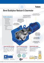
Bevel Buddybox Reducer & Gearmotor Unique Splined Connection ensures more durable and dependable power transmission than typical keyed connections Flexible configurations • Shaft Options: Keyed Hollow Shrink Disc Solid Shaft Keyless Taper Grip Bushing • Mounting Options: ns: Flange Foot Shaft Universal Housing ing Cyclo or Planetary Input provides high overload capacity and exceptional reliability 100% Hardened Steel Internal Components provide long life, smooth operation and superior strength Filtered Breather protects unit lubrication from contaminants Choice of Input Integral motor and IEC...
Open the catalog to page 4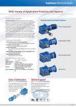
Wide Variety of Application Products and Options Product Description The Bevel Buddybox 4 (BBB4) built by Sumitomo is a robust, state of the art mid-sized family of speed reducers and gearmotors. Building on more than 80 years of successful Cyclo experience in virtually every application and industry, the result is an extremely compact, efficient and reliable unit in a very power-dense package. The BBB4 has a unique combination of features that results in a highly reliable, efficient and durable gearbox. The all-steel internal construction, in conjunction with the Cyclo or planetary gear inputs,...
Open the catalog to page 5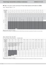
Sumitomo DriveTechnologies Product Range: Standard Motor and Reducer Combinations
Open the catalog to page 6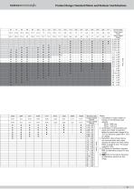
Sumitomo DriveTechnologies Product Range: Standard Motor and Reducer Combinations 1. Calculation of output speed is based on the following input speeds. 50Hz: 1450 rpm 60Hz: 1750 rpm 2. Combination in these tables are guide only. Refer to selection tables for gearmotors (page 50 to 107) or reducers (page129 to 181) for details. 3. Reduction ratios shown above are nominal ratios and output speeds are based on these ratios. Refer to pages 6 and 7 for actual reduction ratio. 4. I I Refer to Sumitomo Hyponic Neo as alternative product for this range.
Open the catalog to page 7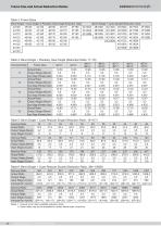
Sumitomo DriveTechnologies Frame Size and Actual Reduction Ratios Table 3: Frame Sizes Notes: 1. Consult us for other available reduction ratios. 2. Some ratios may not be available for certain frame sizes, consult us.
Open the catalog to page 8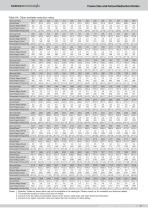
Frame Size and Actual Reduction Ratios Table 6A: Other available reduction ratios. Nominal Ratio 387 Actual Ratio 387,2 Output Stage (Bevel) 3,2 Input Stage (Cyclo) 121 (Intermediate Part×Input Part) (11×11) Nominal Ratio 609 Actual Ratio 609,0 Output Stage (Bevel) 3,5 Input Stage (Cyclo) 174 (Intermediate Part×Input Part) (29×6) Nominal Ratio 893 Actual Ratio 892,5 Output Stage (Bevel) 3,5 Input Stage (Cyclo) 255 (Intermediate Part×Input Part) (17×15) Nominal Ratio 1200 Actual Ratio 1200,0 Output Stage (Bevel) 3,2 Input Stage (Cyclo) 375 (Intermediate Part×Input Part) (25×15) Nominal Ratio 1488...
Open the catalog to page 9
Standard Specifications Sumitomo DriveTechnologies Table 7: Standard Specifications of Motor Note: 4. Consult us if the mounting location contains a slope of 1 degree or more.
Open the catalog to page 10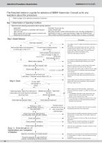
Sumitomo DriveTechnologies The flowchart below is a guide for selection of BBB4 Gearmotor. Consult us for any questions about the procedure. Refer to page 12 for selection procedure of reducers. Step 1: Determination of Operating Conditions Determine the following parameters before starting selection: ■ Application ■ Continuous operation or operation with frequent start and stop ■ Motor capacity (kW) and output speed or reduction ratio ■ Radial load and axial load Operation hours per day Level of shock load Mounting direction (output shaft direction) and mounting configuration Specifications...
Open the catalog to page 12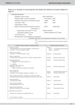
Sumitomo DriveTechnologies Selection Procedure: Gearmotors o Operating Parameters: ■ Application: Chain conveyor ■ Operation pattern: Continuous operation ■ Operation hours per day: 24 operation hours/day ■ Load power: 1,3kW ■ Output speed: 21,6r/min ■ Method of connection with driven shaft:Chain sprocket Initial tension = 0 Sprocket pitch circle radius: R = 70mm Load position: Midpoint of shaft ■Level of shock load : None Motor specifications Power frequency : 50Hz Voltage Brake Others 400V None Outdoor type Ambient conditions Ambient temperature 40oC, indoor ■ Mounting direction (output shaft...
Open the catalog to page 13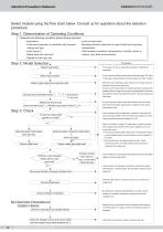
Selection Procedure: Reducers Select models using the flow chart below. Consult us for questions about the selection procedure. Step 1: Determination of Operating Conditions Determine the following conditions before starting selection: Application Level of shock load Continuous operation or operation with frequent Mounting direction (direction of output shaft) and mounting Other ambient conditions (temperature, humidity, indoor or outdoor, and other environments) Load torque TL Radial load and axial load Operation hours per day Step 2: Model Selection Select load factor From pages 14 and 15,...
Open the catalog to page 14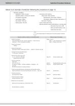
Sumitomo DriveTechnologies Selection Procedure: Reducers Below is an example of selection following the procedure on page 12. ° Operation conditions ■ Application: Chain conveyor ■ Connection with machine : ■ Operation pattern: Continuous operation Output side: Chain sprocket ■ 24 operation hours/day Sprocket pitch circle radius: R=80mm ■ Load torque: 700Nm Load position: Midpoint of shaft; Initial tension = 0 ■ Input speed: 1450 rpm Input side: Coupling ■ Output speed: 16,5 rpm ■ Level of shock load: None ■ Mounting direction (output shaft direction), mounting style : Horizontal, foot mount,...
Open the catalog to page 15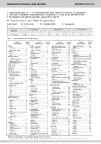
Sumitomo DriveTechnologies Load Factor for Continuous Duty Operation 1. Please refer to Tables 10 & 11 for recommended load factor modifiers for continuous duty applications. 2. The values on the selection tables are based on an operation of 10 hours per day with uniform load. 3. For applications with start/stop operations, please refer to page 15. ■ Recommended Load Factor by Application. [Load Factor] U: Uniform load M: Moderate shock H: Heavy shock Table 10 Reducer Load Factor Table 11 Recommended Load Classifications Cranes (Except for Dry Dock Cranes) Type of Type of Type of Type of APPLICATION...
Open the catalog to page 16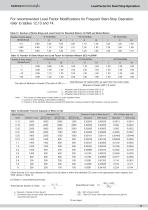
Sumitomo DriveTechnologies Load Factor for Start/Stop Operation Table 12 Number of Starts-Stops and Load Factor for Standard Motors <0,75kW and Brake Motors Check that the CxZ value obtained in Steps [1] to [3] below is within the allowable CZ value in the appropriate motor capacity and %ED values in Table 14. JM : Moment of inertia of motor [kg-m2] GDM2 ; GD2 of motor [Nm2] JL : Converted value at motor shaft; total moment of inertia GDL2 ; Total GD2 at the motor shaft excluding motor [kgf-m2] excluding motor [kg-m2] (To next page)
Open the catalog to page 17All SUMITOMO (SHI) Cyclo Drive Germany GmbH catalogs and technical brochures
 Paramax 9000 series
281 Pages
 Helical Shaft Mount (HSM)
58 Pages
 Bevel Buddybox 4
60 Pages
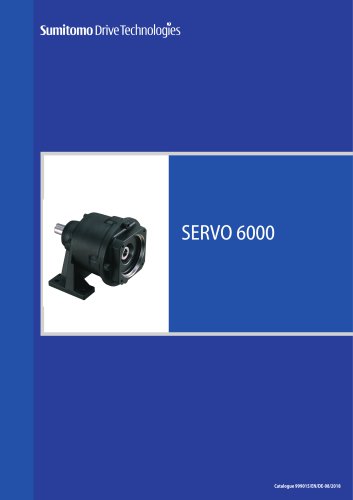 SERVO 6000
38 Pages
 Motion Control DrivesE CYCLO
28 Pages
 Cyclo® BBB5
270 Pages
 Fine Cyclo®
123 Pages
 PARAMAX ® 9000 Series
281 Pages
 Fine Cyclo UA Brochure
2 Pages
 Fine Cyclo Flyer
2 Pages
 Precision Drives Product Catalog
20 Pages
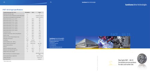 Fine Cyclo F4CF – UA 25
2 Pages
 Fine Cyclo F4CFS–UA 115
4 Pages
 Fine Cyclo F4C–C 25
4 Pages
 Paramax 9000
352 Pages
 Neo Hyponic
120 Pages
 Servo 100
58 Pages
 IB Series catalogues
94 Pages
 Servo 6000 series
6 Pages
 Cyclo® Drive 6000
139 Pages
 Paramax® 9000
352 Pages
 HSM series
58 Pages
 Astero series
186 Pages
 Servo Planetary Gears EPG
6 Pages
 Servo-Planetary Gears
4 Pages
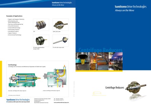 Centrifuge reducers
2 Pages
 Fine Cyclo®
114 Pages









Archived catalogs
 Product overview
16 Pages
- Actuator
- Electric gearmotor
- Planetary gearbox
- Electric actuator
- Coaxial gearhead
- Precision gearhead
- Right angle gearhead
- Direct current gear-motor
- Compact gearhead
- Solid-shaft gearhead
- Hollow-shaft gearhead
- Gear train gear reducer
- Gearbox for industrial applications
- Transmission gearhead
- Multi-stage gearhead
- Single-stage gearhead
- Coaxial gearmotor
- Industrial electric gearmotor
- Right angle electric gearmotor
- AC gear-motor