- Catalogs
- SUMITOMO ELECTRIC Hartmetall GmbH
- Technical Info
Technical Info
1 /55Pages

Technical Info
1 /55Pages
Catalog excerpts

TECHNICAL INFORMATION Technical Guidance | Spare Parts | Index
Open the catalog to page 1
Technical Guidance References Technical Guida
Open the catalog to page 2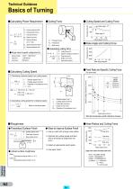
Technical Guidance Basics of Turning Cutting Force Cutting Speed and Cutting Force Principal force (N) Calculating Power Requirement Pc : Net power requirement (KW) f : Feed rate (mm/rev) ap : Depth of cut (mm) η : Machine efficiency Cutting speed (m/min) Rake Angle and Cutting Force K c : Specific cutting force (N/mm2) l Calculating cutting force l Rough value of specific cutting force (Kc) Cutting force (N) Specific cutting force (N/mm2) Chip area (mm2) Depth of cut (mm) Feed rate (mm/rev) v c : Cutting speed (m/min) Rake angle (degree) Feed Rate and Specific Cutting Force Calculating Cutting...
Open the catalog to page 3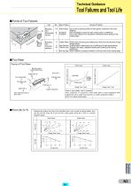
Technical Guidance Tool Failures and Tool Life Forms of Tool Failures Cat. 1~5 Flank Wear Resulting from Mechanical 6 Chipping 7 Fracture causes Resulting from Chemical reactions Cause of Failure Due to the scratching effect of hard grains contained in the work material. Fine breakages caused by high cutting loads or chattering. Due to the impact of an excessive mechanical force acting on the cutting edge. Crater Wear Swaft chips removing tool material as it flow over the top face at high temperatures. Plastic Deformation Cutting edge is depressed due to softening at high temperatures. Thermal...
Open the catalog to page 4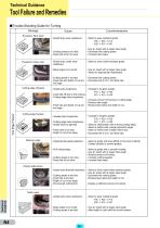
Technical Guidance Tool Failure and Remedies Trouble Shooting Guide for Turning Damage Excessive flank wear Cause - Grade lacks wear resistance. - Cutting speed ist too fast. - Feed rate ist far too slow. - Select a wear resistant grade. P30 a P20 a P10 K20 a K10 a K01 - Use an insert with a larger rake angle. - Decrease the cutting speed. - Increase feed rates. Tool Edge Failure Cutting edge fracture Build-up edge - Select a more crater-resistant grade. - Use an insert with a larger rake angle. - Select an appropriate chipbreaker. - Cutting speed is too fast. - Feed rate and depth of cut are...
Open the catalog to page 5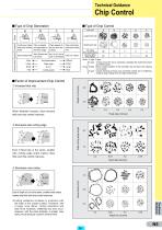
Technical Guidance Chip Control Type of Chip Generation a b Type of Chip Control c Feed rate Large feed rate Shape Influence factor Application Condition Continuous chips Chip is sheared Chips appear to with good surface and separated by be torn from the finish. the shear angle. surface. Steel, Stainless steel Small feed rate Chips crack before reaching the cutting point. NC lathe (For automation) General lathe (For safety) Steel, Stainless steel Steel, Cast iron (Very low Cast iron, Carbon (Low speed) speed, very small feedrate) Work deformation Rake angle D.O.C. Cutting speed Good : C type,...
Open the catalog to page 6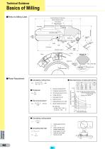
Technical Guidance Basics of Milling Parts of a Milling Cutter External diameter of cutter body External diameter of boss Hole diameter Width of key way Cutter Body Axial rake angle Back locating face Approach angle Setting ring True rake angle Front relief angle Overall height Inclination angle Insert Chip pocket Relief angle Diameter of cutter Locator Setting ring Wiper flat clearance angle Major cutting edge Inward dish Chamfered corner (if trail angle) or wiper flat (if 0°) Radial rake angle l Calculating cutting force ap . ae . vf . Kc 60 5 106 5 η Work- –––s––– piece Alloy steel No. l Relation...
Open the catalog to page 7
Technical Guidance Basics of Milling Functions of the Various Cutting Angles Functions Controls chip removal direction, effects adhesion of the chips and thrust force etc. Approach angle True rake angle (Effective rake angle) The effect of the small approach angle is to reduce the chip thickness and cutting force. Controls cutting performance and ability to retain a cutting edge Influences Rake angles can vary from positive to negative (large to small) with typical combinations of positive and negative, positive and positive or negative and negative configurations. Controls chip thickness and...
Open the catalog to page 8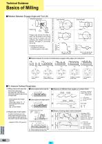
Technical Guidance Basics of Milling Relation Between Engage Angle and Tool Life Insert Rotation Relation to tool life Engage angle denotes the angle by which the full length of the cutting edge comes in contact with the workpiece, with reference to the feed direction. The larger E is, the shorter the tool life. To change the value of E: 1) Increase the cutter size 2) Shift the position of the cutter Small diameter Cutting area by tool life (m3) Large diameter Cutting area by tool life (m3) Relation to cutter position Relation to cutter diameter Workpiece feed direction Engagement angle Engagement...
Open the catalog to page 9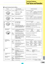
Technical Guidance Tool Failure and Remedies Trouble Shooting Guide for Milling Excessive Flank Wear Basic Remedies P30 a P20 a K20 a K10 Cutting Conditions Excessive Crater Wear Cutting Edge Failure Tool Design Unsatisfactory Machined Surface Finish - Reduce cutting speeds. - Reduce depth-of-cut and feed rate. Cutting Conditions Tool Design Others Unsatisfactory Chip Control Tool Design Cutting Conditions Tool Design Cutting Conditions Steel Finishing Cast Iron Non-Ferrous Alloy ACK200 (Coated Carbide) DA1000 (SUMIDIA) Roughing ACP100 (Coated Carbide) ACK200 (Coated Carbide) DL1000 (Coated Carbide)...
Open the catalog to page 10
Technical Guidance Basics of Endmilling Parts of an Endmill Body Neck Cutter sweep Neck diameter Land width Relief width Diameter Neck length Length of cut Radial relief Radial primary relief angle Radial secondary relief angle Margin width Shank diameter Center hole Shank length Overall length Rake face land width Rake angle Helix angle Radial cutting edge End cutting edge End gash Rounded flute bottom Center hole Flute depth Axial primary relief angle Chip pocket Axial secondary relief angle Ball radius Concavity angle of end cutting edge Calculating Cutting Conditions vc : Cutting speed (m/min)...
Open the catalog to page 11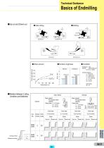
Technical Guidance Basics of Endmilling Up-cut and Dowm-cut Up-cut Workpiece Workpiece Feed l Surface roughness Feed dir. l Condition Workpiece: C50 Endmill: GSX21000C-2D (ø10 mm, 2 teeth) Flank wear width (mm) Relation Between Cutting Condition and Deflection Down-cut Up-cut Cutting conditions: vc = 88 m/min (n = 2.800 min-1) v f = 530 mm/min f z = 0,1 mm/tooth ap = 15 mm ae = 0,5 mm Side milling Work material: Pre-hardened steel (40HRC) Cutting data: vc = 25 m/min ap = 12 mm ae = 0,8 mm Work material: Pre-hardened steel (40HRC) Cutting data: vc = 25 m/min Up ap = 8 mm cut side ae = 8 mm Downcut...
Open the catalog to page 12All SUMITOMO ELECTRIC Hartmetall GmbH catalogs and technical brochures
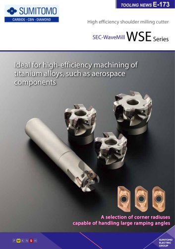 SEC-WaveMillWSE Series
8 Pages
 SR-Reamer Series
36 Pages
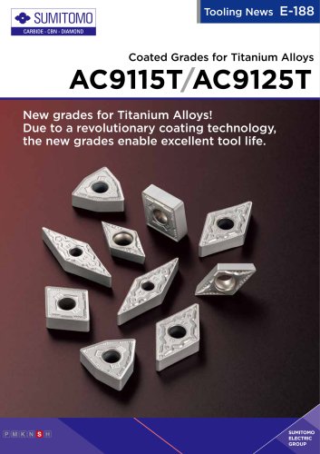 AC9115T/AC9125T
12 Pages
 Highlights 2025-2026
28 Pages
 ERFORMANCE CUTTING TOOLS
1523 Pages
Archived catalogs
 CBN / PCD Tools
113 Pages
 Drilling Tools
69 Pages
 Turning Tools
237 Pages
 Milling Tools
219 Pages
 Cutting Materials
35 Pages
- Chuck
- Solid milling cutter
- Drilling tool
- Milling tool with replaceable insert
- Steel milling cutter
- Metal milling cutter
- Solid drill bit
- Grade
- End mill
- Face milling cutter
- Cast iron milling cutter
- Metal insert
- Indexable insert milling cutter
- Solid carbide milling cutter
- Cutting milling cutter
- Multi-purpose drilling tool
- Shoulder milling cutter
- Coated milling cutter
- Helix angle milling cutter