
- Catalogs
- SUMITOMO Drive Technologies America
- Seisa Compower DP1000 Series Catalog


- Products
- Catalogs
- News & Trends
- Exhibitions
Seisa Compower DP1000 Series Catalog

Seisa Compower DP1000 Series Catalog
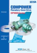
The DP1000 Series Planetary Gear Drive is robust, compact, and simple, offering a modular design with a wide range of specifications. It provides output torque from 0.46kNm to 736kNm and power from 0.2kW to 1200kW, with reduction ratios from 1/16 to 1/1400. Mounting options include foot, flange, and optional shaft mounting.
Standard features include oil bath lubrication, involute planetary gear reduction, and horizontal installation. Suitable for indoor environments with minimal dust and humidity, it operates between -10℃ to 40℃ and under 85% humidity, requiring a well-ventilated location free of corrosive or explosive gases.
Drive units are available in direct motor mount types, simplifying installation. The planetary gear system ensures high strength and rigidity, with equal load distribution and high-pressure angle gears for enhanced tooth strength.
Applicable in industrial settings such as stacker/reclaimer bucket wheel drives and slewing drives, with selection and dimension tables provided.
Includes lubricant and installation guidelines, painting specifications, moment of inertia, and dimensions for spline shafts and motor adapters. Recommended couplings and safety precautions are detailed.
Various motor options include 3-phase induction motors with standard and explosion-proof models, suitable for inverter use with specific voltage and insulation class requirements.
Detailed specifications for planetary gear drives include models like HF Horizontal Flange J Motor Adaptor and VF Vertical Flange JM Motor Adaptor, with torque figures for low-speed shafts and options for shaft mounting, cooling fans, and radial cases.
Outlines the procedure for selecting a reducer, including checking ambient conditions, motor power, shaft speeds, and load conditions. Provides a step-by-step guide to determine the service factor, calculate equivalent transmission power, select nominal reduction ratios, and check dimensions and nomenclature.
References AGMA standards and SEISA’s experience for service factor values, and JIS standards for crane classification.
Includes consulting for special duty or safety specifications, using standard reduction ratios to avoid extra costs and delays, and advises on temperature correction factors and overhang factors for different operating conditions.
Contains extensive tables detailing mechanical power ratings, thermal power ratings, and service factors for various driven machines and operating conditions. Key data includes reduction ratios, high-speed shaft speeds, and allowable radial loads.
Important parameters include the nominal reduction ratio, mechanical power rating, and thermal power rating. Emphasizes the importance of selecting the correct reducer size and type based on specific operating conditions and load requirements.
Provides detailed specifications and dimensions for various types of reducers and drive units, focusing on the DHF type with horizontal flange and inline configurations. Includes tables of dimensions, specifications, and nomenclature for different nominal reduction ratios and sizes.
Outlines nominal reduction ratios ranging from 16 to 1400, with detailed dimension tables for each size. Specifies dimensions for both low-speed and high-speed shafts, including diameter, length, and other critical measurements, and mentions compliance with JIS B1301-1996 (ISO) standards for keys.
Emphasizes that dimensions and specifications may change without notice and highlights the importance of compliance with JIS standards. Provides guidelines for installation, including ambient conditions such as temperature, humidity, and altitude.
Ensures proper installation in well-ventilated locations free of corrosive gases and dust, and suggests using appropriate coupling methods with driven machines, such as gears, chain sprockets, or belts.
Details standard specifications, including capacity range, enclosure type, power source, insulation class, and lubrication method. Specifies the planetary gear system for reduction and provides guidelines for painting and surface preparation.
Lists parts of the drive unit, such as the low-speed shaft, seal cover, case, and motor adapter. Provides codes for motor capacity and torque, indicating the transmission power of the low-speed shaft.
Highlights the importance of maintaining ambient conditions, the necessity of a heating or cooling system for extreme temperatures, and compliance with JIS standards. Notes potential changes in dimensions and specifications without notice.
The motor capacity code should be selected based on the dimensions of the motor adapter as specified on page E-7. Ensures the correct code is chosen for proper motor mounting.
Outlines various drive unit options, including shaft mounting and hollow shaft shrink disk types. Provides a detailed selection table for drive units based on frequency (50Hz or 60Hz), pole count, and speed, with corresponding output torque and service factors.
A comprehensive table is provided to determine the service factor (SF) for different driven machines based on operating hours per day and type of load, essential for ensuring the drive unit can handle operational demands.
An example illustrates the selection process of a drive unit, considering ambient conditions, load power, electric source, and load conditions, concluding with the selection of a specific model (DHFM30-1110-140).
Includes guidelines for checking overhang loads, specifying factors like the overhang member type and radial load position, and provides calculations to ensure the equivalent radial load does not exceed allowable limits.
Advises consulting for special duty requirements or when using internal combustion engines as prime movers, and references standards such as AGMA and JIS for specific applications.
Provides detailed specifications and dimensions for various types of C Drive Units, focusing on the DHGM and DHFM types, designed for horizontal foot and flange mounting with direct motor mounting, covering a range of reduction ratios and motor capacities.
Includes comprehensive dimension tables for different sizes of drive units, detailing measurements crucial for ensuring compatibility and proper installation.
Drive units are equipped with 3-phase induction motors operating at 200V 50/60Hz or 220V 60Hz with a 4-pole configuration, classified under insulation classes B and F.
Keys used in these units comply with the parallel key standard JIS B1301-1996 (ISO).
Outlines various capacity symbols and corresponding kW values, ranging from 0.2 kW to 55 kW, and lists nominal reduction ratios for different sizes.
Provides detailed information on installation and mounting configurations, including horizontal foot and flange mounting options.
Notes that the appearance of the units may vary by size and that dimensions and specifications are subject to change without notice.
1. Painting Specifications: Outlines various painting specifications for different materials and applications, specifying the thickness and type of paint used for different classes of materials.
2. Rust Proofing Standards: Rust proofing treatments are applied to all assembled models before shipment, specifying standard and export rust proofing specifications.
1. Moment of Inertia: Provides tables for the moment of inertia for reducers and motors, categorized by size and reduction ratio.
2. Spline Shaft Specifications: Provides dimensions for spline shafts used in slow-speed applications, conforming to JIS standards.
3. Motor Adapter Dimensions: Includes dimensions for motor adapters according to JEM and IEC standards.
4. Recommended Couplings: Provides recommendations for couplings, including GC and DC types, for different speed shafts.
1. Warranty Period: Specified as 12 months after operation commencement or 18 months after shipment, covering defects due to faulty materials or workmanship.
Outlines warranty conditions, offering repair or replacement for defective parts, with liability limited to the total contract price and excluding indirect or consequential losses.
Excludes issues caused by improper installation, insufficient maintenance, improper use, and force majeure events.
Users must adhere to safety regulations and read the maintenance manual before use, ensuring power sources are off during installation or removal.
Appropriate product selection is crucial, especially for environments with specific requirements like explosion-proof conditions.
Includes a technical data section and an inquiry sheet for the COMPOWER Series Planetary Gear Drive, covering application details and operating conditions.
Catalog excerpts
Affiliated Company of Sumitomo Heavy Industries, Ltd.
Open the catalog to page 1
® Planetary Gear Drive DP1000 Series Gear, Ltd. Affiliated Company of Sumitomo Heavy Industries, Ltd.
Open the catalog to page 3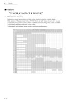
TOUGH, COMPACT & SIMPLE 1 Wide Variation of Lineup Applicable to various specifications with less number of parts by adopting modular design. Wide selection of Planetary Gear Reducer DP1000 Series for better choice of customer's requests. ©Availability of Output Torque from 0.46kNm to 736kNm and Power Range from 0.2kW to 1200kW. ©Applicable to Reduction Ratio from 1/16 to 1/1400. ©Applicable to foot mounting, flange mounting and shaft mounting(option).
Open the catalog to page 8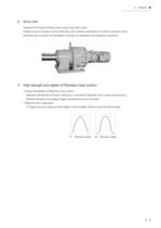
Features ■ ●●●●●●●●●●●●●●●●●● Drive Unit Prepared full lineup of direct motor mount type drive units. Simple layout of models can be made due to the unified combination of reducer and basic motor. Eliminate the necessity for foundation working for installation and alignment operation. High strength and rigidity of Planetary Gear system. ①Equal distribution of Planetary Gear system. Optimum distribution of load to each gear is secured by Planetary Gear system and structure. Slimmer diameter can produce bigger transmission power of torque. ②High pressure angle gear. 27-degree pressure angle provides...
Open the catalog to page 9
■ Features ●●●●●●●●●●●●●●●●●● ■Available Combination Reducer Ratio 5 9 16 90 100 112 125 1010 ● ● ● 18 20 22.4 25 ● 28 31.5 35.5 40 ● ● 45 50 ● 56 63 71 ● 80 ● ● 1020 ● ● ● ● ● ● ● ● ● ● 1030 ● ● ● ● ● ● ● ● ● ● 1040 ● ● ● ○ ○ ● ● ○ ● ● ● ● ● 1050 ● ● ● ○ ○ ● ● ○ ● ● ○ ○ ● ○ ● ○ ○ ● 1060 ● ● ● ○ ○ ● ○ ○ ● ○ ● ● ○ ○ ● ○ ● ○ ○ ● 1070 ● ● ● ○ ○ ● ○ ○ ● ○ ● ○ ● ○ ○ ● ○ ● ○ ○ ● ● ○ ○ ● ○ ○ ● ○ ● ○ ● ○ ○ ● ○ ● ○ ○ ● ● ○ ○ 1080 1090 ○ ○ ● ○ ○ ● ○ ○ ○ ● ○ ● ○ ○ ● ○ ○ ● ● ● ● ● ● ● ● ● ○ ○ ● ○ ○ 1110 ○ ○ ● ● ● ● ● ● ● ● ● ○ ○ ● ○ ○ 1120 ○ ○ ● ● ● ● ● ● ● ● ● ○ ○ ● ○ ○ 1130 ○ ○ ● ● ● ● ● ● ● ● ● ○ ○ ●...
Open the catalog to page 10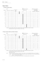
■ Features ●●●●●●●●●●●●●●●●●● Basic Motor 3-Phase Induction Motors 4 Pole Capacity ●Standard Insulation Indoor Type Outdoor Type kW 0.2 0.25 0.4 0.55 0.75 1.1 1.5 2.2 3.0 3.7 5.5 7.5 11 15 18.5 22 30 37 45 55 ○ ○ ○ ○ ○ ○ ○ ○ ○ ○ ○ ○ ○ ○ ○ ○ ○ ○ ○ ○ ○ ○ ○ ○ ○ ○ ○ ○ ○ ○ ○ ○ ○ ○ ○ ○ ○ ○ ○ ○ Corrosionproof Class2 ○ ○ ○ ○ ○ ○ ○ ○ ○ ○ ○ ○ ○ ○ ○ ○ ○ ○ ○ ○ Insulation Class E ● ● ● B ○ ○ ○ ● ● ● ● ● ● ● ● ● ● ● ● ● F ○ ○ ○ ○ ○ ○ ○ ○ ○ ○ ○ ○ ○ ○ ○ ○ ● ● ● ● H ○ ○ ○ ○ ○ ○ ○ ○ ○ ○ ○ ○ ○ ○ ○ ○ ○ ○ ○ ○ ○Manufactured Models Inverter Motors (Constant Torque) Indoor Type Outdoor Type ○ ○ ○ ○ ○ ○ ○ ○ ○ ○ ○ ○ ○...
Open the catalog to page 12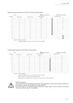
Features ■ ●●●●●●●●●●●●●●●●●● Safety Increased Explosion-proof (eG3) 3-Phase Induction Motor 4 pole Capacity kW 0.2 0.4 0.75 1.5 2.2 3.7 5.5 7.5 11 15 18.5 22 30 37 45 55 Indoor Type Outdoor Type ○ ○ ○ ○ ○ ○ ○ ○ ○ ○ ○ ○ ○ ○ ○ ○ ●Standard Insulation Corrosion-proo Class 2 ○ ○ ○ ○ ○ ○ ○ ○ ○ ○ ○ ○ ○ ○ ○ ○ ○ ○ ○ ○ ○ ○ ○ ○ ○ ○ ○ ○ ○ ○ ○ ○ B ● ● ● ● ● ● ● ● ● ● ● ● ● ○Manufactured Models Insulation Class F ○ ○ ○ ○ ○ ○ ○ ○ ○ ○ ● ● ● Remarks: Continuous Rating Applicable Voltage: 200V, 220V, 350V, 380V, 400V, 440V, 50/60Hz Pressure-tight Explosion-proof (d2G4) 3-Phase Motor 4 pole Capacity kW 0.2 0.4...
Open the catalog to page 13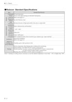
■ Reducer ●●●●●●●●●●●●●●●●●● ■Reducer Standard Specifications Ambient Conditions Reducer Item Lubrication Method Lubricant Reduction Method Shaft Direction Installation Location Ambient Temperature Ambient Humidity Elevation Atmosphere Installation Standard Specification Oil bath lubrication (Some of the upper bearing are lubricated with grease) Refer to the page E-2 Involute Planetary Gear Rotation direction of high speed shaft is the same as output shaft Indoor (Minimal dust and humidity) 10℃40℃ Under 85% Under 1,000 meters Well-ventilated location, free of corrosive gas, explosive gas, vapors...
Open the catalog to page 16
Reducer ■ ●●●●●●●●●●●●●●●●●● ■Construction Drawing DHF (flange type) No. Part Name No. Part Name 1 Low Speed Shaft 6 Internal Gear 2 Seal Cover 7 Sun Gear 3 Case 8 Inter Mediate Cover 4 Bearing 9 High Speed Shaft Cover 5 Planetary Gear 10 High Speed Shaft B―3
Open the catalog to page 17
■ Reducer ●●●●●●●●●●●●●●●●●● ■Nomenclature D Series HG 1090 Shaft Direction and Mounting Style Connection for Motor (Blank) HG Horizontal HF Horizontal Flange J VF Vertical Flange JM Solid Shaft Motor Adaptor D DP 1000 Series Planetary Gear Drive 1120 1130 1140 1150 1160 1170 1180 1190 1200 1210 1220 39.2 53.0 72.6 95.2 128 157 186 275 402 549 736 Remarks: Above figures of Torque show the transmission power of low speed shaft. HY Shaft mounting (Option) B4 Motor Adaptor + Motor 1010 1020 1030 1040 1050 1060 1070 1080 1090 1100 1110 Size Torque kNm 0.46 0.69 1.0 1.6 3.2 5.5 8.6 13.6 15.9 22.6...
Open the catalog to page 18
Reducer ■ ●●●●●●●●●●●●●●●●●● 90 Direction of High Speed Shaft (Blank)Inline Low Speed Shaft (Blank)Solid Shaft Option (Blank)Standard Key type G※ P Right angle (Option Spline Specification F (Option Cooling Fan (Option) View from A ※Following Direction code will be added. Direction code (View from A) U up L R left right D down ※”GR” will apply to VF type in spite of Direction code. T Hollow Shaft Shrink Disk type (Option) R Radial Case (Option) Nominal Ratio 5 9 16 18 20 22.4 25 28 31.5 35.5 40 45 50 56 63 71 80 90 100 112 125 140 160 180 200 224 250 280 315 355 400 450 500 560 630 710 800 900...
Open the catalog to page 19
Determine the Service Factor Calculate Equivalent transmission Determine Size Determine page number indicating Dimension Table Determine Temperature Correction factor Determine overhung factor Calculate Equivalent radial load Complete Selection PM: Actual transmission power or motor SF: Service factor Page B-8~B-9 PE: Equivalent transmission power PN: Mechanical power rating Page B-10~B-25 ■HThe maximum load shall be under the mechanical power rating (PN) of reducer. ■ Page number of relevant Dimension Table is indicated in the Selection K1 : Temperature correction factor K2 : Temperature correction...
Open the catalog to page 20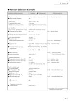
Reducer ■ ●●●●●●●●●●●●●●●●●● ■Reducer Selection Example Conditions and final selections ○Conditions ○ Ambient Condition ■ Check ambient condition indoor, Ambient temperature 25℃ →OK ○ Motor power ○ High speed shaft speed ○ Shaft and mounting positions 22kWCode30 1500r/min Right Angle Shaft, Horizontal Mounting ■Selected item Load condition ○ Type of load, operating hours, usage Uniform load: 14 hours/day, conveyor ■ Determine Service Factor →SF1.25 Reference page No. B-2Standard Specification B-8Service Factor ■ Calculate equivalent transmission power →PE=22×1.25=27.5kW ○ Low speed shaft speed...
Open the catalog to page 21All SUMITOMO Drive Technologies America catalogs and technical brochures
 Fine Cyclo
70 Pages
 PARAMAX ® 9000
281 Pages
 ALTAX NEO
39 Pages
 E CYCLO
28 Pages
 Cyclo® BBB5 Bevel Buddybox®
270 Pages
 IB P2 Catalog
36 Pages
 IB PK1 Catalog
70 Pages
 IB-P1 Catalog
94 Pages

Archived catalogs
 Servo
Servo114 Pages
 SFC Cooling Tower Drives
18 Pages
 Beier® Variator catalog
52 Pages
 Sub-Fractional Hyponic catalog
80 Pages
 Astero® series
95 Pages
 Hedcon catalog
23 Pages
 SPA Series
10 Pages
 HSM complete catalog
64 Pages
 HF320a Complete Catalog
8 Pages
 IB P Type Catalog
68 Pages
 Cyclo® 6000 reducer complete catalog
166 Pages
 Cyclo BBB4 Trifold Brochure
4 Pages
 HF430 Catalog
31 Pages
 Catalogue 999217/EN/DE
186 Pages
 FINE CYCLO
2 Pages
 standardized gear units
135 Pages
 4000 SERIES BEIER VARIATORS
3 Pages
 Centrifuge Reducers
2 Pages
 Motion Control Drives
2 Pages
 IB Series P1 Catalog
94 Pages
 Servo PPG
4 Pages
 Fine Cyclo UA Catalog
4 Pages
 Fine Cyclo D series
30 Pages
 Hansen P4 Multistage (Inch)
86 Pages
 Hansen P4 Multistage (Metric)
140 Pages
 Fine Cyclo Catalog
123 Pages
 IB P1 series
93 Pages
 Paramax® 9000 catalog
352 Pages
 Servo 100 Catalog
114 Pages
 Fine Cyclo®
22 Pages
 Seisa Gear Coupling Catalog
28 Pages


- Electric gearmotor
- Coaxial gearhead
- Precision gearhead
- Right angle gearhead
- Direct current gear-motor
- Compact gearhead
- Solid-shaft gearhead
- Hollow-shaft gearhead
- Gear train gear reducer
- Gearbox for industrial applications
- Transmission gearhead
- Multi-stage gearhead
- Single-stage gearhead
- Industrial electric gearmotor
- Right angle electric gearmotor
- AC gear-motor
- Coaxial gearmotor
- Shaft gearhead
- Helical gear gearhead