
- Catalogs
- SUMITOMO Drive Technologies America
- PARAMAX ® 9000


- Products
- Catalogs
- News & Trends
- Exhibitions
PARAMAX ® 9000

PARAMAX ® 9000
The document provides comprehensive details on the PARAMAX 9000 Series Industrial Gearbox, covering specifications, features, and global locations of Sumitomo's Power Transmission & Controls Group.
The gearbox is available in 26 sizes with output torques ranging from 2.6 to 552 kNm. It features a high thermal capacity due to a new fan cooling system, low noise from optimized gear tooth profiles, and high tooth strength with a 25-degree pressure angle. The universal housing allows for various mounting options.
Standard specifications include oil bath lubrication for horizontal and upright shafts, and pump lubrication for vertical shafts. The gear type is involute external gear, suitable for indoor installations with ambient temperatures between 10 to 40 degrees Celsius. Painting specifications include a primer and final coating in Donau Blue.
The selection process involves determining the service factor, calculating equivalent transmission power, and checking thermal power. The nomenclature includes series, mounting, shaft position, and number of gear stages.
The gearbox is suitable for various applications, including hollow shaft, drop bearing housing, and different mounting options like ceiling, upright wall, and top mount.
The PARAMAX 9000 Series offers a versatile and robust solution for industrial power transmission needs, focusing on efficiency, durability, and adaptability to different operational conditions.
The document outlines specifications for a mechanical power system, focusing on thermal ratings and correction factors. Without a fan, the thermal rating is 48kW, with a correction factor of 0.70, resulting in a power output of 33.6kW. With a fan, the thermal rating increases to 120kW, with a correction factor of 0.73, resulting in a power output of 87.6kW.
The document includes procedures for checking overhung loads, radial load positions, and thrust loads. It specifies an overhang factor of 1.0 and calculates an equivalent radial load of 10.6 kN, within the allowable limit of 29.4 kN.
The document references several standards, including AGMA standards and JIS B8821-1976 for crane classification. It provides service factors for various machinery types based on operating hours and load types.
Selection tables are provided for different reducer configurations, including right angle shaft horizontal, vertical, and upright mountings. The tables include nominal reduction ratios, shaft speeds, and sizes of reducers.
The tables provide detailed information on mechanical and thermal power ratings, nominal reduction ratios, and exact reduction ratios for various configurations. They also include temperature correction factors and notes on lubrication and speed considerations.
Key parameters include the thermal power ratings with and without fans, allowable radial loads, and service factors for different machinery. The document emphasizes consulting for special duty or safety specifications and provides guidelines for selecting the appropriate reducer based on specific requirements.
This document provides detailed specifications and selection tables for mechanical power and thermal power ratings of speed reducers with right angle shaft triple reduction. It includes information on nominal reduction ratios, high-speed and low-speed shaft speeds, and size of reducers.
The document outlines the mechanical and thermal power ratings in kilowatts (kW) for various nominal reduction ratios, including 20, 22.4, 25, 28, 31.5, 35.5, 40, and 45. It provides exact reduction ratios and corresponding high-speed and low-speed shaft speeds in revolutions per minute (r/min).
The document advises on the use of forced oil lubrication for continuous operation at marked values and provides a formula for calculating mechanical power rating (PN) when the high-speed shaft speed is lower than 750 r/min. It also suggests consulting the manufacturer when the high-speed shaft speed exceeds 1800 r/min.
The ratings are applicable for continuous operation at ambient temperatures of 20°C or less. A temperature correction factor is provided for operations outside this range, with different values for models with and without fan cooling units.
Detailed tables are provided for selecting the appropriate size of reducers based on the nominal reduction ratio and shaft speeds. The tables include information on the number of cooling fans required and the dimensions for horizontal, vertical, and upright types.
For high-speed shaft speeds not shown in the tables, interpolation methods should be used. The document also refers to additional tables (B42-B45) for allowable radial and axial loads on each shaft.
This document provides detailed specifications and selection tables for speed reducers, focusing on triple reduction types in horizontal, vertical, and upright configurations. It includes data on nominal and exact reduction ratios, shaft speeds, and mechanical power ratings.
The document outlines various models of speed reducers, each with specific nominal reduction ratios ranging from 40 to 90. It provides exact reduction ratios for each model, indicating precise performance metrics.
The document includes guidelines for selecting the appropriate speed reducer based on shaft speed and mechanical power requirements. It advises on interpolation methods for speeds not explicitly listed and provides formulas for calculating mechanical power ratings when shaft speeds are below 750 r/min.
Recommendations include consulting the manufacturer for high-speed shaft operations over 1800 r/min and using forced oil lubrication for continuous operation in marked models. Temperature correction factors are provided for operations outside the standard ambient temperature of 20°C.
Extensive tables list the mechanical and thermal power ratings for various models, with and without fan cooling units. The tables also specify the number of cooling fans required for each configuration and provide dimensions for each type of reducer.
Key parameters include the nominal reduction ratio, high-speed shaft speed, and the size of the reducer. The document emphasizes the importance of adhering to the specified ratings for safe and efficient operation.
The document outlines the specifications for keys and keyways based on ISO R773-1969 and JIS B1301-1996 standards. It also provides approximate oil quantities, emphasizing that oil should be supplied within the range shown on the oil gauge.
Detailed dimension tables for high-speed shafts and other components are provided for sizes ranging from 9030 to 9085. These tables include measurements for various parts such as A, B, C, D, E, and others, along with oil quantity and weight specifications.
The document advises on the installation of PARAMAX DRIVE, recommending horizontal installation on a rigid base and specifying bolt strength requirements. It also provides guidelines for lubrication, including recommended lubricants from brands like BP, Castrol, and Shell, and specifies the appropriate viscosity based on ambient temperature and operation conditions.
Standard and export rust-proofing specifications are detailed, including the types of paint and coating thicknesses for different environmental conditions. The document specifies the use of acrylic modified alkyd resin and other materials for various painting classes.
Additional technical data includes information on the moment of inertia for right-angle and parallel shafts, supplementary dimensions, and formulas for drive systems. The document also provides guidelines for handling and storage to prevent rust and maintain product integrity.
The document provides detailed technical data on the moment of inertia and GD2 values for parallel shaft configurations. Units are specified in kg-m2 and kgf-m2. The data includes various sizes of reducers and their corresponding nominal reduction ratios, with specific values for each configuration.
The document lists reducer sizes ranging from 9015 to 9136, with nominal reduction ratios from 6.3 to 22.4. Each size has specific moment of inertia values associated with different configurations, such as double, triple, and quadruple reductions.
Detailed dimension drawings are provided for each size of reducer, including measurements for various components such as FS, FA, FB, FC, AS, BS, and others. These dimensions are crucial for installation and compatibility with other mechanical systems.
The PARAMAX DRIVE units feature a torque arm option, designed to prevent the unit from turning due to counter forces. The torque arm is subjected to compression or tensile loads and must be strong enough to handle shock loading during operation. The document outlines the importance of proper installation and the need for sufficient strength in the torque arm mounting legs.
The document provides guidelines for installing the torque arm with the speed reducer housing. It emphasizes the need for mounting the torque arm in an installation hole closer to the application to ensure stability and performance.
This document provides technical specifications and dimensions for various mechanical components, focusing on gear reducers and associated parts. It includes detailed tables and diagrams for different sizes and configurations of shafts, seals, and housing.
- High Speed and Slow Speed Shafts: Detailed dimensions and specifications for high speed and slow speed shafts are provided, including key sizes, approximate mass, and oil quantity.
- Keeper Plate with Washer: Specifications for keeper plates used to retain shafts, including dimensions and bolt specifications. The document notes that the key length is shorter for high speed shafts due to the retaining washer design.
- Double Shaft Seals: Information on the use of double oil seals for enhanced reliability in preventing oil leakage, particularly in environments where leakage could impact production or the environment.
- FKM Seal: Recommended for high-temperature or chemically resistant environments, with specifications for installation dimensions.
- Taconite Seal: Suitable for dusty environments, such as coal conveyors, with details on standard and labyrinth seal types.
- Horizontal and Vertical Mounting: Dimensions for horizontal and vertical mounting configurations are provided, including detailed measurements for various sizes.
- Shaft-End Tapped Hole: Specifications for tapped holes on low speed shaft ends, used for fixing keeper plates.
- Use FKM seals for environments with temperatures above 60 degrees Celsius or requiring chemical resistance.
- Consider double oil seals for applications where oil leakage could have severe consequences.
- In dusty environments, use taconite seals to prevent dust ingress and protect oil seals.
This document provides technical specifications and options for various types of shaft reductions and mounting configurations, including parallel and right-angle shaft reductions. It includes detailed dimensions, specifications for internal components, and options for environmental adaptations.
The document lists dimensions for different sizes of parallel and right-angle shaft reductions, including triple and quadruple stage reductions. Key dimensions such as A, B, C, D, and key sizes are provided in millimeters.
The internal backstop is mounted directly on the intermediate shaft of the reducer, simplifying the application device by eliminating the need for a torque arm, bearing, oil seal, and specialized lubrication. It allows the inner race to rotate in a single direction only.
Designed for outdoor environments exposed to rain or water splash, this breather prevents water ingress into the reducer. It features a stainless steel element and an internal cylindrical section.
Suitable for dusty environments, this breather uses a long nipple to elevate the unit and a dustproof cover to prevent dust accumulation.
Used in high-humidity environments, this breather contains an absorbent agent to prevent moisture penetration, protecting the reducer from rust and lubrication oil deterioration.
Recommended for corrosive environments, this valve is made of stainless steel and offers better corrosion resistance than bronze valves. It is available in various sizes with detailed dimensions provided.
The document advises consulting the manufacturer when using certain configurations, such as upward vertical shafts or right-angle shafts, to ensure proper application and performance.
Catalog excerpts

Worldwide Locations U.S.A Sumitomo Machinery Corporation of America (SMA) 4200 Holland Blvd. Chesapeake,VA 23323,U.S.A. TEL (1)757-485-3355 FAX (1)757-485-7490 Canada SM Cyclo of Canada, Ltd. (SMC) 1453 Cornwall Road,Oakville, Canada ON L6J 7T5 TEL (1)905-469-1050 FAX (1)905-469-1055 France SM-Cyclo France SAS (SMFR) 8 Avenue Christian Doppler, 77700 Serris, France TEL (33)164171717 FAX (33)164171718 Italy SM-Cyclo Italy Srl (SMIT) Via dell' Artigianato 23, 20010 Cornaredo (MI), Italy TEL (39)293-481101 FAX (39)293-481103 Singapore Sumitomo (SHI) Cyclo Drive Asia Paci c Pte. Ltd. (SCA) 15 Kwong Min Road, Singapore 628718 TEL (65)6591-7800 FAX (65)6863-4238 Philippines Sumitomo (SHI) Cyclo Drive Asia Paci c Pte. Ltd. (SMPH) C4 & C5 Bldg. Granville Industrial Complex Governor’s Drive, Bo. Bancal, Carmona, Cavite 4116 Philippines TEL (63)2-584-4921 FAX (63)2-584-4922 TEL (63)46-430-3591 TEL (63)46-482-0580 TEL (63)46-482-0581 Mexico SM Cyclo de Mexico, S.A. de C.V. (SMME) Av. Desarrollo 541, Col. Finsa, Guadalupe, Nuevo León, México, CP67132 TEL (52)81-8144-5130 FAX (52)81-8144-5130 Spain SM-Cyclo Iberia, S.L.U. C/Gran Via n° 63 bis planta primera, o cina 1B 48011 Bilbao - Vizcaya, Spain TEL (34)944-805389 Brazil Sumitomo Industrias Pesadas do Brasil Ltda. (SHIB) Rodovia do Acucar (SP-075) Km 26 Itu, Sao Paulo, Brasil TEL (55)11-4886-1000 FAX (55)11-4886-1000 United Kingdom SM-Cyclo UK Ltd. (SMUK) Unit 29, Bergen Way, Sutton Fields Industrial Estate, Kingston upon Hull, HU7 0YQ, East Yorkshire, United Kingdom TEL (44)1482-790340 FAX (44)1482-790321 Chile SM Cyclo de Chile, Ltda. (SMCH) San Pablo 3507, Quinta Normal, Santiago, Chile TEL (56)2-892-7000 FAX (56)2-892-7001 Turkey SM Cyclo Turkey Güç Aktar m Sis. Tic. Ltd. Sti. (SMTR) Büyükdere Çay rba Cd. Dede Yusuf Sk. No:11, 34453 Sar yer Istanbul, Turkey TEL (90)216-384-4482 FAX (90)216-384-4482 Malaysia SM-Cyclo of Malaysia Sdn. Bhd. (SMMA) No.7C, Jalan Anggerik Mokara 31/56, Kota Kemuning, Seksyen 31, 40460 Shah Alam, Selangor D.E., Malaysia TEL (60)3-51210455 FAX (60)3-51210578 China Sumitomo (SHI) Cyclo Drive China, Ltd. (SCT) 11F,SMEG Plaza, No.1386 Hongqiao Road, Changning District, Shanghai, China (P.C.200336) TEL (86)21-3462-7877 FAX (86)21-3462-7922 Indonesia PT. SM-Cyclo Indonesia (SMID) Cikarang Jalan Sungkai Blok F 25 No.09 K, Delta Silicon III, Lippo Cikarang, Bekasi, Indonesia TEL (62)21-2961-2100 FAX (62)21-2961-2211 Hong Kong SM-Cyclo of Hong Kong Co.,Ltd. (SMHK) Rm 1301, CEO Tower, 77 Wing Hong Street, Cheung Sha Wan, Kowloon, Hong Kong TEL (852)2460-1881 FAX (852)2460-1882 Thailand SM-Cyclo (Thailand) Co., Ltd. (SMTH) 195 Empire Tower, 21st Fl., Unit 2103-4, South Sathorn Rd., Yannawa Sathorn, Bangkok 10120, Thailand TEL (66)2-670-0998 FAX (66)2-670-0999 Guatemala SM Cyclo de Guatemala Ensambladora, Ltda. (SMGT) Parque Industrial Unisur, 0 Calle B 19-50 Zona 3, Bodega D-1 Delta Bárcenas en Villa Nueva, Guatemala TEL (502)6648-0500 FAX (502)6631-9171 Colombia SM Cyclo Colombia, S.A.S. Carrera 11, No.93A-53, Of ce 203, Bogotá, Colombia TEL (57)1-3000673 Germany Sumitomo (SHI) Cyclo Drive Germany GmbH (SCG) Cyclostraße 92, 85229 Markt Indersdorf, Germany TEL (49)8136-66-0 FAX (49)8136-5771 Korea Sumitomo (SHI) Cyclo Drive Korea, Ltd. (SCK) Royal Bldg. 9F Rm.913, 5 Danju-Dong, Chongro-Ku, Seoul, Korea 110-721 TEL (82)2-730-0151 FAX (82)2-730-0156 Taiwan Tatung SM-Cyclo Co., Ltd. (TSC) 22 Chungshan N. Road 3rd., Sec. Taipei, Taiwan 104, R.O.C. TEL (886)2-2595-7275 FAX (886)2-2595-5594 Austria Sumitomo (SHI) Cyclo Drive Germany GmbH (SCG) SCG Branch Austria Of ce Gruentalerstraße 30A, 4020 Linz, Austria TEL (43)732-330958 FAX (43)732-331978 Australia Sumitomo (SHI) Hansen Australia Pty. Ltd. (SHAU) 181 Power Street Glendenning NSW 2761, Australia TEL (61)2-9208-3000 FAX (61)2-9208-3050 India Sumi-Cyclo Drive India Pvt. Ltd. (SMIN) Survey No.130, Hissa No.02, Jeevan Nagar, Off MumbaiBangalore bypass, Tathawade, Pune-411 033, India TEL (91)20-6674-2900 FAX (91)20-6674-2901 Industrial Gearbox Headquarter ThinkPark Tower, 1-1 Osaki 2-chome, Shinagawa-ku, Tokyo 141-6025, Japan 9000 Series Industrial Gearbox Japan Sumitomo Heavy Industries, Ltd. ThinkPark Tower, 1-1 Osaki 2-chome, Shinagawa-ku, Tokyo 141-6025, Japan TEL (81)3-6737-2511 FAX (81)3-6866-5160 Belgium Belgium, Netherlands, Luxemburg Hansen Industrial Transmissions NV Leonardo da Vincilaan 1-3 2650 Edegem, Belgium TEL (32)3-450-12-11 Power Transmission & Controls Group Argentina SM Cyclo de Argentina S.A. (SMAR) Ing. Delpini, 2236Area de Promocion el Triangulo, Partido Malvinas Argentinas Grand Bourg, Buenos Aires, Argentina B1615KGB TEL (54)3327-45-4095 FAX (54)3327-45-4099 Vietnam SM-Cyclo (Vietnam) Co., Ltd. (SMVN) Factory 2B, Lot K1-2-5,Road No.: 2-3-5A, Le Minh Xuan Industrial Park, Binh Chanh Dist., HCMC, Vietnam. TEL (84)8-37-663-709 FAX (84)8-37-663-710
Open the catalog to page 1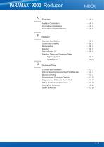
Available Combination Introduction of Application Introduction of Applied Product Reducer Standard Speci cations Construction Drawing Nomenclature Selection Service Factor SF Selection Tables and Dimension Tables Right Angle Shaft Parallel Shaft Technical Data Lubricant and Installation Painting Speci cations and Rust Proof Standard Moment of Inertia Supplementary Dimension Drawing Supplementary Matters to Hollow Shaft Hollow Shaft Related Dimensions Cooling Fan Dimension Option Dimension
Open the catalog to page 2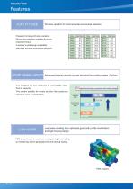
Features JUST FIT SIZE 26 sizes variation for most accurate economical selection. Prepared full range 26 sizes variation. Fitness size selection available for every requested torque. Customer's wide design availability with most accurate economical selection. LARGER THERMAL CAPACITY Advanced thermal capacity by new designed fan cooling system. (Option) New designed fan and conducted air cowling gain larger thermal capacity. This system bene ts for severe situation like continuous operation, even if compact size. 87% higher thermal rating comparison with existing design New design fan and hood...
Open the catalog to page 3All SUMITOMO Drive Technologies America catalogs and technical brochures
 Fine Cyclo
70 Pages
 ALTAX NEO
39 Pages
 E CYCLO
28 Pages
 Cyclo® BBB5 Bevel Buddybox®
270 Pages
 IB P2 Catalog
36 Pages
 IB PK1 Catalog
70 Pages
 IB-P1 Catalog
94 Pages

Archived catalogs
 Servo
Servo114 Pages
 SFC Cooling Tower Drives
18 Pages
 Beier® Variator catalog
52 Pages
 Sub-Fractional Hyponic catalog
80 Pages
 Astero® series
95 Pages
 Hedcon catalog
23 Pages
 SPA Series
10 Pages
 HSM complete catalog
64 Pages
 HF320a Complete Catalog
8 Pages
 IB P Type Catalog
68 Pages
 Cyclo® 6000 reducer complete catalog
166 Pages
 Cyclo BBB4 Trifold Brochure
4 Pages
 HF430 Catalog
31 Pages
 Catalogue 999217/EN/DE
186 Pages
 FINE CYCLO
2 Pages
 standardized gear units
135 Pages
 4000 SERIES BEIER VARIATORS
3 Pages
 Centrifuge Reducers
2 Pages
 Motion Control Drives
2 Pages
 IB Series P1 Catalog
94 Pages
 Servo PPG
4 Pages
 Fine Cyclo UA Catalog
4 Pages
 Fine Cyclo D series
30 Pages
 Hansen P4 Multistage (Inch)
86 Pages
 Hansen P4 Multistage (Metric)
140 Pages
 Fine Cyclo Catalog
123 Pages
 IB P1 series
93 Pages
 Paramax® 9000 catalog
352 Pages
 Servo 100 Catalog
114 Pages
 Fine Cyclo®
22 Pages
 Seisa Gear Coupling Catalog
28 Pages
 Seisa Compower DP1000 Series Catalog
145 Pages


- Electric gearmotor
- Planetary gearbox
- Coaxial gearhead
- Precision gearhead
- Right angle gearhead
- Direct current gear-motor
- Compact gearhead
- Solid-shaft gearhead
- Hollow-shaft gearhead
- Gear train gear reducer
- Gearbox for industrial applications
- Transmission gearhead
- Multi-stage gearhead
- Single-stage gearhead
- Industrial electric gearmotor
- Right angle electric gearmotor
- AC gear-motor
- Coaxial gearmotor
- Shaft gearhead
- Helical gear gearhead