- Catalogs
- SUMITOMO Drive Technologies America
- IB PK1 Catalog
IB PK1 Catalog
1 /70Pages

IB PK1 Catalog
1 /70Pages
Catalog excerpts
Sumitomo DriveTechnologtes IB Series PK1 Type Planetary Gear Reducer for Servo Motor Right Angle Type
Open the catalog to page 1
Standard Specification, Construction, • 4 and Mechanism Selection Table 1 (Frame Size Combination Table for Each Motor Rated Speed) • 5 Selection Table 2 (Frame Size Combination Table for Each Servo Motor Manufacturers) • 7 2. Yaskawa Electric Corporation • 8 3. Mitsubishi Electric Corporation • 10 Selection Table 3 (Rating Table) • 11 (Allowable External Rating) • 13 Durability Check of Output Shaft Part • 58 Formula for Calculation of Moment of Inertia and GD2 ••• 61 Formula for Calculation of Moment of Inertia, Load Torque, and Acceleration Torque • 62 Moment of Inertia (at Motor Shaft) •...
Open the catalog to page 2
Bearing of output (Angular contact ball bearings) - Planetary gear of output Pinion Gear Spiral Bevel Gear
Open the catalog to page 3
Large diameter precision angular bearing, supporting output shaft, allows large radial load with compact casing. Spiral Bevel gear concept allows compact design ("L"-dimmension) 1. Comparison with similar ratio and ratings. 2. Our survey estimate. Output shaft Variation Three variations available to match customers' needs. Optimal selection possible for your application. Flange shaft type ■ Solid shaft type with keyway Assembly Simple assembly. Directly connect servo motor and reducer with bolt (provided by customer) after delivery. Tighten motor shaft with hexagon wrench. Ready for immediate...
Open the catalog to page 4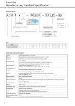
Nomenclature, Standard Specification Nomenclature Type and Frame Size 110 PK 120 130 Special Input Method Backlash Symbol 6 min specification: LB 15 min specification: LD Motor Flange Code Mounting (Flange Attachment Type) Output Shaft Type Solid Shaft (Keyless) Solid Shaft (with Key) Flange Shaft Output Shaft Direction (Unlimited Mounting Direction) Ratio Ratio Actual reduction ratio Standard Specification Backlash Efficiency 86% or more at rated output torque (with reduction ratio 6, 8, 11, 15, 27) Noise Level 70dB(A) 0.5m *Varies depending on models and mounting condition. Lubrication system...
Open the catalog to page 5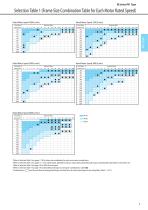
Rated Motor Speed 1000 [r/min] Rated Motor Speed 4000 [r/min] Servo Moto Capacity [W] *Refer to Selection Table 2 (on pages 7-10) for frame size combination for each servo motor manufacturer. *Refer to Selection Table 3 (on pages 11, 13) for rated torque, allowable maximum input speed, allowable peak torque, and allowable radial load for each frame size. *Refer to Selection Table 3 (on page 12) for %ED of each speed. *Refer to Selection Table 3 (on page 11) for allowable peak torque at startup for combinations marked
Open the catalog to page 6
*Torque necessary at the input side to rotate the reducer at no load condition. *This is the representative value when the ambient temperature is 200C.
Open the catalog to page 7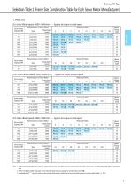
1. FANUC Ltd. i is Series (Rated speed: 6000~1500r/min) •• • Applies to torque at rated speed Note 1: Refer to Selection Table 3 (on pages 11-13) for rated torque, allowable maximum input speed, allowable peak torque, and allowable radial load for each frame size. 2: Refer to Selection Table 3 (on page 11) for allowable peak torque at startup for combinations marked •. 3: Combination in [””] must be used that the avarage load torque is limited to be less than rated torque in the rating table (Table 1-1, P.11).
Open the catalog to page 8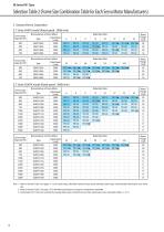
Note 1: Refer to Selection Table 3 (on pages 11-13) for rated torque, allowable maximum input speed, allowable peak torque, and allowable radial load for each frame size. 2: Refer to Selection Table 3 (on page 11) for allowable peak torque at startup for combinations marked •. 3: Combination in [””]must be used that the avarage load torque is limited to be less than rated torque in the rating table (Table 1-1, P.11).
Open the catalog to page 9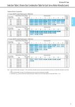
Yaskawa Electric Corporation 1-7 Series SGM7P model (Rated speed: 3000r/min) Note 1: Refer to Selection Table 3 (on pages 11-13) for rated torque, allowable maximum input speed, allowable peak torque, and allowable radial load for each frame size. 2: Refer to Selection Table 3 (on page 11) for allowable peak torque at startup for combinations marked •. 3: Combination in must be used that the avarage load torque is limited to be less than rated torque in the rating table (Table 1-1, P.11).
Open the catalog to page 10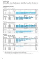
3. Mitsubishi Electric Corporation MELSERV0-J4 HG-KR Series (Rated speed: 3000r/min) Note 1: Refer to Selection Table 3 (on pages 11-13) for rated torque, allowable maximum input speed, allowable peak torque, and allowable radial load for each frame size. 2: Refer to Selection Table 3 (on page 11) for allowable peak torque at startup for combinations marked •. 3: Combination in [””]must be used that the avarage load torque is limited to be less than rated torque in the rating table (Table 1-1, P.11).
Open the catalog to page 11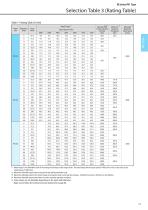
Table1-1 Rating Table (SI Unit) 1: Rated torque is the allowable value of the average load torque at the output shaft. The rated torque for the input speed of 1000 r/min or less is the same as the rated torque of 1000 r/min. *2: Maximum allowable torque when startup and stop during operation cycle. *3: Maximum allowable value of the shock torque at emergency stop or external shock torque. Should be less than 1,000 times in one lifetime. *4: Maximum allowable input speed when not under constant operation condition. *5: Some values are not allowable depending on the input shaft diameter. Make sure...
Open the catalog to page 12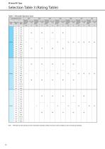
Input Speed (r/min) Frame Size Allowable continuous operation period Allowable continuous operation period Allowable continuous operation period Allowable continuous operation period Allowable continuous operation period Allowable continuous operation period Allowable continuous operation period Note: ^Allowable constant operation hours for intermittent operation condition (Consult us when exceeding or when continuously operating).
Open the catalog to page 13
Table 2 External Load (SI Unit) PK1 Type *1: Radial load is the value applied to the middle of the output shaft (at axial load). *2: Axial load is the value applied to the center of the output shaft (at radial load). Multiply radial load locating factor to the value in the above table when the radial load is applied to locations other than the middle of the output shaft. 0 5 10 15 20 25 30 35 40 45 50 55 60 65 70 75 80 85
Open the catalog to page 14All SUMITOMO Drive Technologies America catalogs and technical brochures
 Fine Cyclo
70 Pages
 PARAMAX ® 9000
281 Pages
 ALTAX NEO
39 Pages
 E CYCLO
28 Pages
 Cyclo® BBB5 Bevel Buddybox®
270 Pages
 IB P2 Catalog
36 Pages
 IB-P1 Catalog
94 Pages
 Fine Cyclo Catalog
123 Pages
 Hansen P4 Multistage (Metric)
140 Pages
 Hansen P4 Multistage (Inch)
86 Pages
 Fine Cyclo D series
30 Pages
 Fine Cyclo UA Catalog
4 Pages
 Servo PPG
4 Pages
 IB Series P1 Catalog
94 Pages
 Motion Control Drives
2 Pages
 Centrifuge Reducers
2 Pages
 4000 SERIES BEIER VARIATORS
3 Pages
 standardized gear units
135 Pages
 FINE CYCLO
2 Pages
 Catalogue 999217/EN/DE
186 Pages
 HF430 Catalog
31 Pages
 Cyclo BBB4 Trifold Brochure
4 Pages
 Cyclo® 6000 reducer complete catalog
166 Pages
 IB P Type Catalog
68 Pages
 HF320a Complete Catalog
8 Pages
 HSM complete catalog
64 Pages
 SPA Series
10 Pages
 Hedcon catalog
23 Pages
 Astero® series
95 Pages
 Sub-Fractional Hyponic catalog
80 Pages
 Beier® Variator catalog
52 Pages
 Servo
Servo114 Pages
 SFC Cooling Tower Drives
18 Pages


Archived catalogs
 IB P1 series
93 Pages
 Paramax® 9000 catalog
352 Pages
 Servo 100 Catalog
114 Pages
 Fine Cyclo®
22 Pages
 Seisa Gear Coupling Catalog
28 Pages
 Seisa Compower DP1000 Series Catalog
145 Pages


- Electric gearmotor
- Coaxial gearhead
- Precision gearhead
- Direct current gear-motor
- Right angle gearhead
- Compact gearhead
- Solid-shaft gearhead
- Gear train gear reducer
- Hollow-shaft gearhead
- Gearbox for industrial applications
- Transmission gearhead
- Right angle electric gearmotor
- Multi-stage gearhead
- Shaft gearhead
- Single-stage gearhead
- Coaxial gearmotor
- AC gear-motor
- Compact gear-motor
- Helical gear gearhead