- Catalogs
- SUMITOMO Drive Technologies America
- Fine Cyclo Catalog
Fine Cyclo Catalog
1 /123Pages

Fine Cyclo Catalog
1 /123Pages
Catalog excerpts

Sumitomo DriveTechnologies Fine Cyclo® Zero Backlash Precision Gearboxes
Open the catalog to page 1
Copyright Sumitomo (SHI) Cyclo DriveGermany GmbH 2018. All rights reserved. Copying, including extracts, is only permitted with our approval. The information in this catalogue has been checked for correctness with extreme care. However, no liability can be accepted for any incorrect or incomplete information. We reserve the right to make modifications.
Open the catalog to page 3
Fine Cyclo Sumitomo DriveTechnologTes 1 The Fine Cyclo reducer 2 3.1 Reduction ratio and acceleration torque 9 4 Explaining the technical details 18 5.4 No-load running torque NLRT 29 6.4 No-load running torque NLRT 65 6.8 Assembly specifications and tolerances 70 7.4 No-load running torque NLRT 83 7.8 Assembly specifications and tolerances 89
Open the catalog to page 5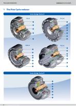
Fine Cyclo Introduction 1 The Fine Cyclo reducer Inner design Series A FC-A Inner design Series D
Open the catalog to page 6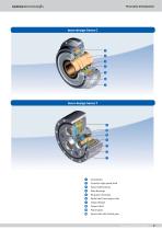
Fine Cyclo Introduction Inner design Series C Inner design Series T O Cycloid disc © Eccentric high speed shaft © Inputshaftbearing © Main Bearings © Ringgear(housing) © Radialshaftsealoutputside © Outputflange © Output shaft © Planetgears © Input shaft with helical gear
Open the catalog to page 7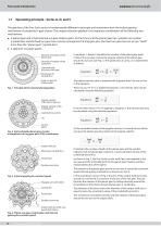
Fine Cyclo Introduction Sumitomo DriveTechnologies 1.1 Operating principle - Series A, D, and C Thegearboxofthe FineCycIo series ^fundamentally different in principle and mechanism from the helical gearing mechanism ofcompetitors1 gear motors. The unique reduction gearbox is an ingenious combination ofthefollowing two mechanisms: • A planet gearand a fixed internal sun gear (hollow gear). On the Fine Cyclo the planet gear has cycloidal cam motion (cycloid disc) and thefixed sun gear has a circulararrangement of ring gear pins.Thefixed sun gear has one ortwo "teeth" more than the "planet gear"...
Open the catalog to page 8
Fine Cyclo Introduction Sumitomo DriveTechnologTes 1.2 Operating principle Series T The Series T gearboxes are double stage and differfrom the single stage series in having 3 eccentrics, driven by the input shaft with spur teeth. The cycloid discs are driven via 3 eccentric shafts and not directly byone eccentric input shaft. The pins and the eccentric shafts in the output shaftare evenly spaced on a circle, which is concentric to the axis ofthe sun gear. The pins transmitthe rotation ofthe planet gear by rolling internally around the circumference ofthe bores ofeach planet gearor cycloid disc....
Open the catalog to page 9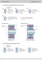
Fine Cyclo Introduction Sumitomo DriveTechnologies 1.3 Speed ratio and rotation direction - Series A, D, and C Output shaft Ring gear housing Input shaft Gear reduction s lnput:lnputshaft u Output:Outputshaft ' Fixed: Ring gear housing n = -1/i Gear reduction Input: Input shaft Output: Ring gear housing Fixed: Output shaft n = 1/(i+1) Gear reduction Input: Output shaft Output: Ring gear housing Fixed: Input shaft n=i/(i+1) Output flange rotates n = Speedratio = (outputspeed/inputspeed) indicates the possible opposite direction) i = reduction ratio 1.4 Speed ratio and rotation direction Series...
Open the catalog to page 10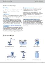
Fine Cyclo Introduction Sumitomo DriveTechnologTes 1.5 Features and advantages Compact design The high reduction ratios, in one or a maximum oftwo stages, allow for extremely compact designs with a long lifetime. Moreover, due to the different versions available, these gearboxes can be optimally integrated into the machine environment. Simple installation The Series A, D, and C gearboxes are lubricated for life, fully sealed and maintenance-free. Convenient and simple motor mounting is also taken account of in all ranges. Precise positioning In more and more applications, fast cycle speeds and...
Open the catalog to page 11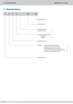
Fine Cyclo Introduction Sumitomo DriveTechnologies 2 Nomenclature F -Reduction ratio Standard version: - Shape of ring gear housing: Cylindrical - Symbol forCycIo Bearing: Withoutoutputsidebearing: - Integrated cross roller bearing: 1 Integrated tapered roller bearing: 2 Tapered roller bearings and output shaft: 3 Integrated angular ball bearing: 4
Open the catalog to page 12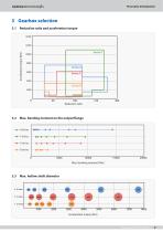
Fine Cyclo Introduction Sumitomo DriveTechnologTes Reduction ratio 3 Gearbox selection3.1 Reduction ratio and acceleration torque 14000 12000 10000 z 0) 3 8000 o 4—' c o 2 6000 ai 3.3 Max. hollow shaft diameter Fine Cyclo 991333 02/2018
Open the catalog to page 13
Fine Cyclo Introduction Sumitomo DriveTechnologies 3.4 Reduction ratio and outer diameter A-Series Special feature: Both a reduction kit without an output side bearing as well as fully sealed versions and a gearbox with output shaft instead ofoutput flange a e available Optional: Available with motor adapter, customer-specific input shaft or output flange and other modification •: available reduction ratio
Open the catalog to page 14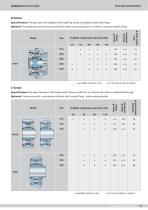
Fine Cyclo Introduction Sumitomo DriveTechnologTes D-Series Special feature: Thegearboxes are supplied with matching clamp ring adapter and motorflang Optional: The gearboxes can also be purchased with other mounting options or without customer-specific flang . « S-S s i •: available reduction ratio a. A.: Housing shape on request C-Series Special feature: The largediameterofthe hollow shaftallows an effective use ofspaceforcable or media feed-through Optional: Customer-specific customisation of input shaft, output flang , and housing possible : available reduction ratio a. A.: Housing shape...
Open the catalog to page 15
Sumitomo DriveTechnologies T-Series Special feature: Gearboxes with high positioning and path accuracy, even under highly flu tuating dynamic conditions Optional: Fitting of motors without key with clamp ring design possible 12 •: available reduction ratio Max. motor shaft-0 with keyway (clamp ring design on request) 14 17 22 28 28 35 35
Open the catalog to page 16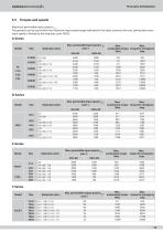
Fine Cyclo Introduction Sumitomo DriveTechnologTes 3.5 Torques and speeds Maximum permissible input speed n, ED The gearbox can be used within the maximum input speed range indicated in the table, however, the max. permissible mean input speed is limited by the load duty cycle (%ED). A-Series Model Size Reduction ratio i Max. permissible input speed n [min-1] torque for emergency stop Reduction ratio i Max. permissible input speed n1 ED [min-1] 50% ED 100% ED Max. acceleration torque [Nm] Max. torque for emergency stop C-Series Model
Open the catalog to page 17All SUMITOMO Drive Technologies America catalogs and technical brochures
 Fine Cyclo
70 Pages
 PARAMAX ® 9000
281 Pages
 ALTAX NEO
39 Pages
 E CYCLO
28 Pages
 Cyclo® BBB5 Bevel Buddybox®
270 Pages
 IB P2 Catalog
36 Pages
 IB PK1 Catalog
70 Pages
 IB-P1 Catalog
94 Pages
 Hansen P4 Multistage (Metric)
140 Pages
 Hansen P4 Multistage (Inch)
86 Pages
 Fine Cyclo D series
30 Pages
 Fine Cyclo UA Catalog
4 Pages
 Servo PPG
4 Pages
 IB Series P1 Catalog
94 Pages
 Motion Control Drives
2 Pages
 Centrifuge Reducers
2 Pages
 4000 SERIES BEIER VARIATORS
3 Pages
 standardized gear units
135 Pages
 FINE CYCLO
2 Pages
 Catalogue 999217/EN/DE
186 Pages
 HF430 Catalog
31 Pages
 Cyclo BBB4 Trifold Brochure
4 Pages
 Cyclo® 6000 reducer complete catalog
166 Pages
 IB P Type Catalog
68 Pages
 HF320a Complete Catalog
8 Pages
 HSM complete catalog
64 Pages
 SPA Series
10 Pages
 Hedcon catalog
23 Pages
 Astero® series
95 Pages
 Sub-Fractional Hyponic catalog
80 Pages
 Beier® Variator catalog
52 Pages
 Servo
Servo114 Pages
 SFC Cooling Tower Drives
18 Pages


Archived catalogs
 IB P1 series
93 Pages
 Paramax® 9000 catalog
352 Pages
 Servo 100 Catalog
114 Pages
 Fine Cyclo®
22 Pages
 Seisa Gear Coupling Catalog
28 Pages
 Seisa Compower DP1000 Series Catalog
145 Pages


- Electric gearmotor
- Planetary gearbox
- Coaxial gearhead
- Precision gearhead
- Direct current gear-motor
- Right angle gearhead
- Compact gearhead
- Solid-shaft gearhead
- Gear train gear reducer
- Hollow-shaft gearhead
- Gearbox for industrial applications
- Transmission gearhead
- Right angle electric gearmotor
- Multi-stage gearhead
- Shaft gearhead
- Single-stage gearhead
- Coaxial gearmotor
- AC gear-motor
- Compact gear-motor
- Helical gear gearhead