
- Catalogs
- SUMITOMO Drive Technologies America
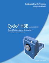
- Cyclo Helical Buddybox (HBB) Gearmotor and Reducer Full Catalog


- Products
- Catalogs
- News & Trends
- Exhibitions
Cyclo Helical Buddybox (HBB) Gearmotor and Reducer Full Catalog

Cyclo Helical Buddybox (HBB) Gearmotor and Reducer Full Catalog
The Cyclo® HBB Helical Buddybox is a speed reducer and gearmotor solution designed for demanding applications. It combines Cyclo® technology with helical gear output for efficient and reliable performance. The modular design allows for a compact product with flexible output speed and torque combinations. The patented Taper-Grip® bushing system offers easy, backlash-free torque transmission and self-aligning capabilities.
- Ratios: 11:1 up to 26,000:1
- Torque Capacity: Up to 75,800 in. lbs.
- Horsepower: 1/8 to 40 HP
- Mounting Options: Hollow Shaft, Flange, Face
- Motor Standards: NEMA, IEC, JIS, UL, CSA, CE
- Cycloidal speed reduction technology for quiet and efficient operation
- Modular design with interchangeable housings
- Double output seals for leak-free operation
- Taper-Grip® Bushing for easy installation and removal
- CEMA Screw Conveyor Drive option for quick conversion
The Cyclo® HBB is suitable for various applications including material handling, conveyors, baggage handling, shredders, hoist drives, and food processing.
Selection is based on horsepower and torque requirements at the output shaft. The catalog provides guidance on choosing the most efficient reducer for specific applications, considering factors like application type, hours of operation, motor horsepower, loading conditions, and mounting position.
Service factors are used to adjust for specific conditions and operating requirements. The Cyclo® HBB is rated for 10-hour daily service under uniform loads, with a capacity for 300% momentary intermittent shock loads.
The Cyclo® speed reducer has a high thermal rating due to its smooth operation, which exceeds its mechanical capacity and minimizes heat-related limitations.
The Taper-Grip® bushing is a keyless, torque transmission device that simplifies mounting and removal, resists fretting and corrosion, and requires no special shaft preparation.
The Taper-Grip® bushing is designed to transmit maximum torque without weakening the shaft, making it suitable for high start-up and reversing applications. It is compatible with all Taper-Grip® products.
The standard torque arm assembly is detailed in the reducer and gear-motor dimensions sections. It should be mounted at 90 degrees to a line from the attachment point to the reducer and the center of the output bore, with a variance of plus or minus 15 degrees. It must be mounted in tension, not compression. Optional torque arms include T-type and flange-mount (banjo) types.
The Cyclo® HBB speed reducers have specific shaft rotation directions depending on the reduction ratio. Standard input speeds are 1750 and 1165 RPM, with variations affecting horsepower and torque ratings. The reducers have high thermal capacity due to their smooth operation.
These include a 3-phase capacity range, totally enclosed fan-cooled enclosures, and specific power supply and insulation classes. The reducers are designed for continuous operation and have specific lubrication and seal requirements.
Recommended for indoor use with minimal dust and humidity, within specified temperature and humidity ranges, and at elevations under 3,281 ft. The atmosphere should be well-ventilated and free of corrosive or explosive gases.
Various mounting positions are available, with additional configurations detailed in the appendix.
To select a speed reducer, gather application data, choose a mounting position, select a frame size based on load classification and service factor, verify dimensions, choose a bushing bore size, and configure a model number.
Service factors vary based on the duration of service and load classification, with specific recommendations for different applications.
Includes details on configuring model numbers based on various specifications such as output shaft orientation, mounting style, input connection, and frame size.
- Output Torque: Ranges from 2,610 in-lbs to 75,800 in-lbs depending on the model and configuration.
- Input Horsepower: Varies from 0.125 HP for low inertia applications to 29.5 HP for higher torque requirements.
- Frame Sizes: Multiple frame sizes are available, each with specific dimensions and mounting options.
- Selection tables are provided for both single and double reduction models, detailing the output RPM and corresponding input HP and output torque for each frame size and ratio.
- Dimensions for each model are specified, including NEMA C-Face dimensions and other critical measurements.
- A torque limiting device is recommended to protect the unit or driven machine, especially in high inertia applications.
- Dimensions are subject to change without notice unless certified, and certified prints are available upon order receipt.
- Single Reduction: Output RPM ranges from 4.20 to 20.0, with corresponding input HP and output torque values provided for each frame size.
- Double Reduction: Output RPM ranges from 0.0661 to 4.81, with detailed input HP and output torque values for each configuration.
- Ensure correct selection of frame size and mounting position based on application requirements.
- Consult factory for certified dimensions and any changes to specifications.
- Step 1: Collect application data, including application type, hours of operation, motor horsepower, desired output speed, mounting position, and load specifications.
- Step 2: Choose a mounting position from the provided table.
- Step 3: Select a frame size based on load classification and desired output speed.
- Step 4: Verify dimensions to ensure the selected frame size is appropriate.
- Step 5: Choose a bushing bore size from the stock table.
- Step 6: Select additional options such as brakemotor or washdown modifications.
- Step 7: Configure a model number using the gathered information.
- Class I: For steady loads with moderate shock, up to 10 hours per day.
- Class II: For steady loads with moderate shock, 24 hours per day.
- Class III: For moderate to heavy shock loads, 24 hours per day.
- Specifications: Each table lists gearmotor specifications for different HP ratings, including 2 HP, 3 HP, 5 HP, 7.5 HP, 10 HP, 15 HP, 20 HP, 25 HP, 30 HP, and 40 HP. The specifications include output speed, output torque, service factor, AGMA class, and frame size ratio.
- Mounting Positions: The gearmotors can be mounted in four different positions (Y1, Y2, Y3, Y4), allowing for flexibility in installation.
- Service Factor and AGMA Class: The service factor indicates the gearmotor's capacity to handle overloads, while the AGMA class provides a standard for gear quality and performance.
- Dimensions: Detailed dimensions for each gearmotor model are referenced on pages 3.52–3.57, although these pages are not included in the provided text.
The document provides detailed technical specifications and installation procedures for Cyclo® HBB Speed Reducers and Taper-Grip® Bushing systems. These systems are designed for high shock load capacity and are warranted for two years.
Cyclo® HBB Speed Reducers offer a 300% momentary intermittent shock load capacity. They are suitable for applications involving frequent start-stop, braking, or reversing. The document advises consulting the factory for model selection in such cases.
Taper-Grip® Bushing Installation:
1. Inspect and clean the driven shaft.
2. Remove the safety cover and cap screws from the bushing.
3. Slide the thrust collar onto the bushing and apply anti-seize paste.
4. Thread the bushing into the hub and create a gap between the thrust collar and bushing flange.
5. Tighten the cap screws and install the unit on the driven shaft.
1. Align the bushing with the driven shaft and slide the unit onto the shaft.
2. Tighten the capscrews using a torque wrench in a star-pattern.
3. Install the safety cover and follow the operating manual instructions.
1. Support the unit externally and ensure a gap between the thrust collar and bushing flange.
2. Apply liquid penetrant to the capscrews and remove them.
3. Release the bushing using a hammer and slide the unit off the shaft.
Shaft Connections: Ensure proper alignment and avoid overtightening belts or chains.
Shaft Rotation: Single reduction units have the same rotation direction for high and low-speed shafts, while double reduction units have opposite directions.
Input Speeds: Standard input speeds are 1750 and 1165 RPM.
Thermal Capacity: The reducers have high thermal ratings exceeding mechanical capacity.
Ensure horizontal and vertical units are mounted in exact planes. Avoid overfilling with oil to prevent leakage and overheating.
Details on motor types, power ratings, and mounting specifications are provided, emphasizing the need for adequate ventilation and space for maintenance.
The document provides comprehensive guidelines for the installation, operation, and maintenance of Cyclo® HBB Speed Reducers and Taper-Grip® Bushing systems, ensuring optimal performance and safety.
The document provides detailed specifications for Cyclo® HBB brakemotors, including standard wiring connections and varistor specifications. It outlines the combination of brakemotor inertia and the applicable brake models for different motor frame sizes. The document also includes tables for standard brake rectifiers and power modules, specifying model numbers and part numbers for various voltage modules.
The appendix details lubrication requirements for Cyclo® HBB units, emphasizing the need to fill oil-lubricated models with the correct lubricant before operation. It specifies oil and grease types suitable for different ambient temperatures and provides guidelines for oil replenishment and change intervals. The document highlights that grease-lubricated models are maintenance-free upon shipment.
Sumitomo warrants Cyclo® HBB Speed Reducers for two years from the date of shipment, covering defects in material or workmanship. The warranty is contingent upon proper installation, maintenance, and operation within specified limits.
The document includes several figures illustrating normal and fast brake actions at various voltages. Tables provide detailed specifications for varistors, standard oils, and greases, as well as oil fill quantities for different models and mounting positions.
The document lists contact details for Sumitomo Machinery Corporation's worldwide locations, including offices in the United States, Canada, Mexico, South America, Europe, and Asia.
Catalog excerpts
WORLDWIDE LOCATIONS Sumitomo Machinery Corporation of America Headquarters & Manufacturing 4200 Holland Boulevard Chesapeake, VA 23323 Tel: 757-485-3355 • Fax: 757-485-7490 www.smcyclo.com E-mail: [email protected] U.S. Sales and Support Mexico Europe Midwest Monterrey Sumitomo Machinery Corporation of America 175 West Lake Drive Glendale Heights, IL 60139 Tel: 630-752-0200 • Fax: 630-752-0208 SM-Cyclo de Mexico S.A. de C.V. Av. Desarrollo No. 541 Parque Industrial Finsa Guadalupe, NL, Mexico CP 67114 Tel: 011-52-81-8144-5130 • Fax: 011-52-81-8369-3699 Austria Belgium France Germany Italy Spain Sweden United Kingdom West Sumitomo Machinery Corporation of America 2375 Railroad Street Corona, CA 92880-5411 Tel: 951-340-4100 • Fax: 951-340-4108 Toronto (East) SM-Cyclo of Canada, Ltd. 1045 South Service Road, West Oakville, Ontario, Canada L6L 6K3 Tel: 905-469-1050 • Fax: 905-469-1055 Vancouver (West) SM-Cyclo of Canada, Ltd. 740 Chester Road, Annacis Island, Delta B.C., Canada V3M 6J1 Tel: 604-525-5403 • Fax: 604-525-0879 Montreal SM-Cyclo of Canada, Ltd. 2862 Blvd. Daniel-Johnson Laval, Quebec, Canada H7P 5Z7 Tel: 450-686-8808 • Fax: 450-686-8000 SM-Cyclo de Mexico, S.A. de C.V. Privada Ceylan No. 59-B Bis Colonia Industrial Vallejo Delegacion Azcapotzalco, DF Mexico 02300 Tel: 011-52-55-5368-7172 • Fax: 011-52-55-5368-6699 Guadalajara SM-Cyclo de Mexico S.A. de C.V. Calle Broca No. 2605, Bodega 4 Parque Alamo Industrial Tlaquepaque, Jal, Mexico 44490 Tel: 011-52-33-3675-43-69 • Fax: 011-52-33-3675-4418 South America Brazil SM-Cyclo Redutores do Brasil Ltda. Av. Fagundes Filho, 191 Ed. Houston Office Center–c j. H123 CEP: 04304-010–São Paulo, Brazil Tel: 011-55-11-5585-3600 • Fax: 011-55-11-5585-9990 Asia China Hong Kong Indonesia Korea Malaysia Philippines Singapore Taiwan Thailand Vietnam Chile HELICAL BUDDYBOX Speed Reducers and Gearmotors featuring Keyless Taper-Grip® Bushing Other Locations SM-Cyclo de Chile Ltda. San Pablo 3507 Comuna de Quinta Normal - Santiago, Chile Tel: 011-562-892-7000 • Fax: 011-562-892-7001 Cyclo® HBB Cyclo® HBB Canada Mexico City Australia India New Zealand SM-Cyclo de Chile Ltda. Calle 8, Manzana N2, Sitio 1 Sector La Negra, Antofagasta, Chile Tel: 011-565-556-1611 • Fax: 011-565-556-1616 Japan Sumitomo Heavy Industries, Ltd. Power Transmission & Controls Group ThinkPark Tower, 1-1, Osaki 2-chome, Shinagawa-ku, Tokyo 141-6025 Japan Tel: 011-813-6737-2511 • Fax: 011-813-6866-5160 For Worldwide contact information: www.sumitomodrive.com SM-Cyclo de Chile Ltda. Camino a Coronel Km 10, #5580, Modulo 3-A Comuna: San Pedro de la Paz – Concepción, Chile Tel: 011-41-246-98-06/07 • Fax: 011-41-246-98-08 Argentina SM-Cyclo de Argentina SA Manuel Montes de Oca 6719 B1606 BMG, Munro Buenos Aires, Argentina Tel: 011-54-11-4765-5332 • Fax: 011-54-11-4765-5517 Catalog 07.601.50.005; Supersedes Catalog 07.601.50.004 ©2012 Sumitomo Machinery Corporation of America Printed in USA Reducers & Gearmotors World Headquarters CATALOG 07.601.50.005
Open the catalog to page 1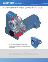
Cyclo® HBB Helical Buddybox Rugged Helical Output, Modular Cyclo® Input, Compact Size Bottling/Baking Water Treatment Steel hypoid gear technology, maintenance-free grease lubrication and a compact modular housing makes the Hyponic® an efficient performer in the food industry. Each of these Sumitomo Paramax® speed reducers helps pump up to 13 million gallons a day at this state-of-the-art wastewater treatment facility in the City of Clearwater, Florida. A 15-hp Beier mechanical variable speed drive with electric remote control provides an adjustable, steady speed range for this 350-ft. oven band...
Open the catalog to page 2
Cyclo® HBB Helical Buddybox Rugged Helical Output, Modular Cyclo® Input, Compact Size Bottling/Baking Water Treatment Steel hypoid gear technology, maintenance-free grease lubrication and a compact modular housing makes the Hyponic® an efficient performer in the food industry. Each of these Sumitomo Paramax® speed reducers helps pump up to 13 million gallons a day at this state-of-the-art wastewater treatment facility in the City of Clearwater, Florida. A 15-hp Beier mechanical variable speed drive with electric remote control provides an adjustable, steady speed range for this 350-ft. oven band...
Open the catalog to page 3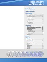
Speed Reducers and Gearmotors Table of Contents 1. General Information 2. Speed Reducers How to Select . . . . . . . . . . . . . . . . . . . . . . . . . . . . . . . .2.2 Configure a Model Number (Nomenclature) . . . .2.4 AGMA Load Classifications . . . . . . . . . . . . . . . . . . . .2.6 Selection Tables . . . . . . . . . . . . . . . . . . . . . . . . . . . . .2.8 Single Reduction . . . . . . . . . . . . . . . . . . . . . . . . . . . . . . .2.8 Horizontal Mounting . . . . . . . . . . . . . . . . . . . . . . . . .2.8 Vertical Mounting . . . . . . . . . . . . . . . . . . . . . . . . . . .2.10...
Open the catalog to page 4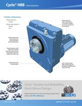
Cyclo® HBB Helical Buddybox Flexible configurations • Shaft Options: hollow Utilizes all Cyclo® input modifications: C-Face input, integral gearmotor, brakemotor or servomotor • Mounting Options: flange face Double output seals prevent lubricant leaks and protect from contamination Patented keyless, steel Taper-Grip® bushing allows for quick and easy mounting and removal. Installs from either side Patented universal housing design Cyclo® input provides high overload capacity, exceptional reliability and long service life Cyclo® Quality and Reliability, Shaft Mount Design High performance steel...
Open the catalog to page 5
Parallel Shaft Helical Gearbox with Cyclo® Reducer Input Product Description Sumitomo’s Cyclo® Helical Buddybox (Cyclo® HBB) speed reducers and gearmotors provide innovative shaft mounted drive solutions for demanding services. The Cyclo® HBB combines the quiet, efficient and reliable performance of the Cyclo® technology input with the rugged helical gear output. The modular design provides a compact, efficient product and the most flexible range of output speed and torque combinations available. Sumitomo's patented Taper Grip® bushing system enhances the Cyclo® HBB value by offering a simple...
Open the catalog to page 6All SUMITOMO Drive Technologies America catalogs and technical brochures
 Fine Cyclo
70 Pages
 PARAMAX ® 9000
281 Pages
 ALTAX NEO
39 Pages
 E CYCLO
28 Pages
 Cyclo® BBB5 Bevel Buddybox®
270 Pages
 IB P2 Catalog
36 Pages
 IB PK1 Catalog
70 Pages
 IB-P1 Catalog
94 Pages

Archived catalogs
 Servo
Servo114 Pages
 SFC Cooling Tower Drives
18 Pages
 Beier® Variator catalog
52 Pages
 Sub-Fractional Hyponic catalog
80 Pages
 Astero® series
95 Pages
 Hedcon catalog
23 Pages
 SPA Series
10 Pages
 HSM complete catalog
64 Pages
 HF320a Complete Catalog
8 Pages
 IB P Type Catalog
68 Pages
 Cyclo® 6000 reducer complete catalog
166 Pages
 Cyclo BBB4 Trifold Brochure
4 Pages
 HF430 Catalog
31 Pages
 Catalogue 999217/EN/DE
186 Pages
 FINE CYCLO
2 Pages
 standardized gear units
135 Pages
 4000 SERIES BEIER VARIATORS
3 Pages
 Centrifuge Reducers
2 Pages
 Motion Control Drives
2 Pages
 IB Series P1 Catalog
94 Pages
 Servo PPG
4 Pages
 Fine Cyclo UA Catalog
4 Pages
 Fine Cyclo D series
30 Pages
 Hansen P4 Multistage (Inch)
86 Pages
 Hansen P4 Multistage (Metric)
140 Pages
 Fine Cyclo Catalog
123 Pages
 IB P1 series
93 Pages
 Paramax® 9000 catalog
352 Pages
 Servo 100 Catalog
114 Pages
 Fine Cyclo®
22 Pages
 Seisa Gear Coupling Catalog
28 Pages
 Seisa Compower DP1000 Series Catalog
145 Pages


- Planetary gearbox
- Coaxial gearhead
- Precision gearhead
- Right angle gearhead
- Direct current gear-motor
- Compact gearhead
- Solid-shaft gearhead
- Hollow-shaft gearhead
- Gear train gear reducer
- Gearbox for industrial applications
- Transmission gearhead
- Multi-stage gearhead
- Single-stage gearhead
- Industrial electric gearmotor
- Right angle electric gearmotor
- AC gear-motor
- Coaxial gearmotor
- Shaft gearhead
- Helical gear gearhead