- Catalogs
- SUCO Robert Scheuffele GmbH & Co. KG
- Electromagnetic clutches and brakes
Electromagnetic clutches and brakes
1 /12Pages

Electromagnetic clutches and brakes
1 /12Pages
Catalog excerpts
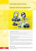
www.suco.de Electromagnetic clutches and brakes General technical explanations Electromagnetic clutches and brakes from SUCO are, among other things, notable for straightforward design and ease of installation. When these clutches and brakes are correctly selected, they are trouble-free, require no maintenance, and are extremely reliable. SUCO clutches are dry running clutches. In order for them to operate correctly, grease and oil must be kept away from their friction surfaces. These electromagnetic clutches and brakes can be installed on anges or shafts. Flange-mounted versions require a suitable ange surface. The magnet component of the shaft-mounted models must be secured against rotation. The torque support must not be rigidly xed. Electromagnetic clutches and brakes require a DC power supply. They normally operate on a 24 VDC supply, but can also be supplied for other voltages (6, 12, 48 and 190 VDC). As standard, the power supply is via a 2-core cable 0.4 m long. Other cable lengths and connectors are available on request. Due to their simple, modular design, electromagnetic clutches and brakes are easy to select. The standard form of output is an axial drive with a bore and keyway, which passes through a ange. Variants are shown on subsequent pages. Customer-specic versions are available on request. Several examples of customer-specic versions are shown following the standard models. Fields of application Among many other applications, SUCO electromagnetic clutches and brakes are used in construction machines, agricultural machinery, machine tools, pumps and compressors, centrifuges, belt conveyors and cleaning machines. 22
Open the catalog to page 1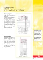
www.suco.de Construction and mode of operation Electromagnetic clutches The stator body 1 contains the eld coil 2 , which is a copper coil cast in synthetic resin. The clutch is activated by applying a direct current to the eld coil. This creates a magnetic eld (red), which electromagnetically attracts the armature disc 4 towards the input drive hub 7 with its friction lining 3 , and so allows torque to be transmitted from the input side to the output. The axially-located output drive hub 6 separates from the input side when the current is cut off. A return spring 5 ensures that the armature...
Open the catalog to page 2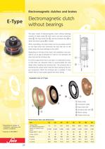
www.suco.de E-Type Electromagnetic clutches and brakes Electromagnetic clutch without bearings The basic model of electromagnetic clutch without bearings consists of stator body 1 with cast-in coil and connection cable 2 , the input drive hub 3 , and the armature disc 4 to which the return spring 5 is riveted. When assembling, the stator body must be accurately centred on the input drive hub, otherwise the hub may rub on the stator body and cause damage to the clutch. 5 Depending on the size of the clutch, the installation must provide for an air gap of between 0.2 and 0.5 mm between the drive...
Open the catalog to page 3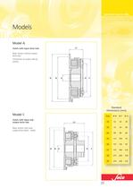
www.suco.de Models Model A L1 Clutch with input drive hub Basic version without output drive hub Connection to output side by screws D B d F H Standard Dimensions [mm] Model C Size d H 63 46 90 80 60 112 100 76 137 125 95 175 160 120 08 215 200 158 09 25 72 07 F 29 06 B 42 05 D 52 04 Basic version with axial output drive (shaft - shaft) ØH 02 L2 ØF 03 Clutch with input and output drive hub ØB 270 250 210
Open the catalog to page 4
www.suco.de G-Type Electromagnetic clutches and brakes Electromagnetic clutch with bearing The basic model of electromagnetic clutch with bearing consists of stator body 1 with cast-in coil and connection cable 2 , the input drive hub 3 with support bearing, and the armature disc 4 to which the return spring 5 is riveted. Because it contains a bearing, it is not necessary to centre the stator body on the input drive hub when using this model. Depending on the size of the clutch, the installation must provide for an air gap of between 0.2 and 0.5 mm between the drive hub and the armature disc....
Open the catalog to page 5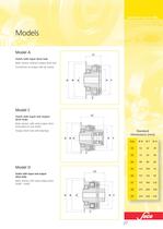
www.suco.de Models Model A L1 Clutch with input drive hub Basic version without output drive hub Connection to output side by screws D B d H F Model C L2 Clutch with input and output drive hubs Basic version with axial output drive (mounted on one shaft) Output drive hub with bearings Standard Dimensions [mm] D B d H F Size 27 46 90 80 60 112 100 76 137 125 95 175 160 120 215 200 158 09 H F 63 08 d 72 07 B 29 06 D 42 05 Basic version with axial output drive (shaft - shaft) 52 04 Clutch with input and output drive hubs ØH 03 L3 ØF 02 Model D ØB 270 250 210
Open the catalog to page 6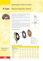
www.suco.de B-Type Electromagnetic clutches and brakes Electromagnetic brakes The basic model of electromagnetic brake consists of stator body 1 with cast-in coil and connection cable 2 , and the armature disc 4 to which the return spring 5 is riveted. The friction lining 3 is bonded directly to the stator body. The stator body must be installed so that it is concentric with the output side. Depending on the size of the brake, the installation must provide for an air gap of between 0.2 and 0.5 mm between the friction lining and the armature disc. If a SUCO output drive hub is not used, it is...
Open the catalog to page 7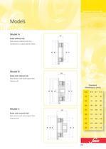
www.suco.de Models Model A L1 Brake without hub Basic version without drive hub Connection to output side by screws D B Model B H F L2 Brake with internal hub Basic version with axial output drive Internal hub Standard Dimensions [mm] D B d H F H 29 63 46 90 80 60 112 100 76 137 125 95 175 160 120 215 200 158 09 F 72 08 B d 29 07 D 42 06 External hub 52 05 Basic version with axial output drive ØH 04 Brake with external hub ØF 03 L3 ØB 02 Model C Size 270 250 210
Open the catalog to page 8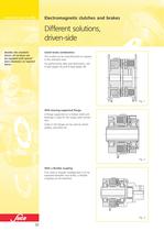
www.suco.de Electromagnetic clutches and brakes Different solutions, driven-side Besides the standard bores, all versions can be supplied with special bore diameters or tapered bores. Clutch-brake combination This model can be manufactured on request in the standard sizes. For performance data and dimensions, see E-Type (page 24) and B-Type (page 28). Fig. 1 With bearing-supported ange A ange supported on a hollow shaft and bearings is used for the output side connection. Holes in the ange can be used to attach pulleys, sprockets etc. Fig. 2 With a exible coupling If an axial or angular misalignment...
Open the catalog to page 9All SUCO Robert Scheuffele GmbH & Co. KG catalogs and technical brochures
 M.10 Accessories
6 Pages
 E.7 Accessories
4 Pages
 SUCO Transmission Technology
38 Pages
 SUCO Medical Applications
6 Pages
 M.4 Pressure switches hex 27
10 Pages
 M.3 Pressure switches hex 24
12 Pages
 M.7 Pressure switches 30 A/F
5 Pages
 M.9 Vacuum switches
4 Pages
 SUCO Pressure Monitoring
178 Pages
 T.6 Accessories
4 Pages
 SUCO Plasma cleaning
5 Pages
 ESI Oil, Gas & Subsea
8 Pages
 ESI General Product range
8 Pages
 Product Overview 2020
6 Pages
 ESI Pressure Sensors
88 Pages


Archived catalogs
 Pressure transmitter
6 Pages
 SUCO Thread adapter
2 Pages
 Pressure switches PLUS
6 Pages
 SUCO Small wind turbines
4 Pages
 SUCO Agriculture
6 Pages
 SUCO Construction Machines
6 Pages
 SUCO Water Applications
6 Pages
 Vakuum Switch
4 Pages
 Pressure Switch hex 24
10 Pages
 Pressure Switch hex 27
12 Pages
 Pressure Switch 30 A/F
4 Pages
 Centrifugal cluches and brakes
16 Pages
 TRANSMISSION TECHNOLOGY
40 Pages
 PRESSURE MONITORING
64 Pages


- Pressure transmitter
- Analog pressure transmitter
- Pressure switch
- Waterproof pressure transmitter
- Membrane pressure transmitter
- Stainless steel pressure transmitter
- Relative pressure transmitter
- Mechanical pressure switch
- Waterproof pressure switch
- Gas pressure transmitter
- Liquid pressure transmitter
- Threaded pressure transmitter
- Process pressure transmitter
- Sensitive element pressure transmitter
- DC pressure transmitter
- IP65 pressure transmitter
- Diaphragm pressure switch
- IP67 pressure transmitter
- Compact pressure transmitter
- Piezoresistive pressure transmitter