
Catalog excerpts

TECHNICAL DATA • Control specially designed for use in harsh mobile applications • Debug device of the controller • External: optional data ash and F-RAM options • Component deployment C, Matlab1), and IEC61131-3 (logi.CAD 3) • Flexible programming in C, Matlab1) or IEC61131-3 (logi.CAD 3) • Suitable for safety-related applications up to SIL2 according to IEC 61508:20101), PL d according to EN ISO 13849-1:20151), AgPL d Cat 2. according to DIN EN ISO 251191) or ASIL B according to ISO 262621) • Mating plug • Integrated into STW's openSYDE software platform Sensor-Technik Wiedemann GmbH • 59 outputs 1) Scheduled feature Subject to change without notice Am Bärenwald 6 87600 Kaufbeuren Germany +49 8341 9505-0 info.stw@wiedemann-group.com www.stw-mm.com • Coprocessor i.MX 6 with Linux (optional)
Open the catalog to page 1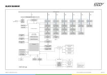
BLOCK DIAGRAM Subject to change without notice
Open the catalog to page 2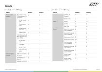
Variants Variant features of the ESX.4cl-ag Feature Processor and memory Variant features of the ESX.4cl-ag Variant 1 32 bit Inneon Aurix TC399 multicore CPU, @ 300 MHz 6.5 MB internal RAM 16 MB internal Flash 16 MB external data Flash Communication interface Subject to change without notice Real Time Clock (RTC) CAN, from 100 kbit/s to 1 Mbit/s Digital/PWM high side 8 output OPHSP4A Digital/PWM high side 16 output OPHSP2A PWM half bridge output OPHB10A Digital/PWM low side output OPL4A Digital/PWM low side output OPL0A5 Sensor supply voltage 5 V Sensor supply voltage 5 ... 12 V
Open the catalog to page 3
Variants Available options of the ESX.4cl-ag Options Communication Interface Subject to change without notice LIN in accordance to LIN specification 2.2 A (with equipped i.MX6 the LIN option is not available)
Open the catalog to page 4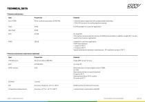
TECHNICAL DATA Processor and memory Type • External system supervisor with programmable watchdog • 12 bit A/D converter for analog signal processing 15.5 MB available for customer application Data Flash On-chip RAM This memory serves as system memory for BIOS stack and data. In addition roughly 80 % can be used for the customer application. Available for customer application. FRAM data retention: • 11 years at 105 °C • 121 years at 85 °C Typical endurance according to manufacturer: 1013 read/write cycles at 125 °C Processor and memory coprocessor (optional) Type eMMC memory Write endurance...
Open the catalog to page 5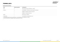
TECHNICAL DATA Communication interfaces Type Maximum quantity CAN 2.0B, baud rate from 100 kbit/s to 1 Mbit/s 100/1000BASE-T1 (100 Mbit/s/1 Gbit/s Single Pair Ethernet) 100BASE-T1 (100 Mbit/s Single Pair Ethernet) Baud rate up to 115 kBit/s • LIN and RS232 share the same connector pins, i.e. either RS232 or LIN is available, but not both. • If the i.MX6 coprocessor is equipped, RS232 is operated by the i.MX6. Subject to change without notice
Open the catalog to page 6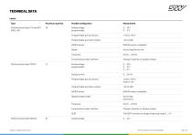
TECHNICAL DATA Inputs Type Maximum quantity Possible configuration Analog voltage programmable Programmable pull-up resistor Programmable pull-down resistor NAMUR sensor NAMUR sensor compatible Incremental encoder interface Change of position or angular change Analog voltage programmable Analog current Programmable pull-up resistor Programmable pull-down resistor NAMUR sensor NAMUR sensor compatible Digital (voltage mode) Active high Achtive low Incremental encoder interface Change of position or angular change Full SENT interface at voltage measuring range 0 ... 5 V Analog voltage...
Open the catalog to page 7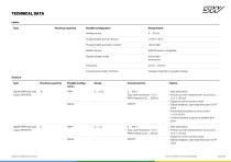
TECHNICAL DATA Inputs Type Maximum quantity Possible configuration Analog current Programmable pull-up resistor Programmable pull-down resistor NAMUR sensor NAMUR sensor compatible Digital (voltage mode) Active high Achtive low Incremental encoder interface Change of position or angular change Outputs Type Maximum quantity Possible configuration Digital/PWM high side output OPHSP2A 0 ... 100 % Duty cycle resolution < 0.1 % PWM frequency 20 ... 1000 Hz • High side switch • Precise current measurement, accuracy is ±2.3 % ±35 mA • Supports current control mode • Digital feedback, open load...
Open the catalog to page 8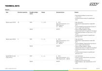
TECHNICAL DATA Outputs Type Maximum quantity Possible configuration Feature • Automated shutdown on overcurrent > 7.5 A ±1.5 A • Combine several outputs for parallel operation Digital/PWM low side output OPL4A Subject to change without notice 0 ... 100 % Duty cycle resolution < 0.1 % PWM frequency 20 ... 1000 Hz 0 ... 100 % Duty cycle resolution < 0.1 % PWM frequency 20 ... 1000 Hz 0 ... 100 % Duty cycle resolution < 0.1 % PWM frequency 20 ... 1000 Hz • High side switch • Optimized for digital operation mode (ON/ OFF) • Current feedback,measurement accuracy is ±25.0 % (gain) ±100 mA...
Open the catalog to page 9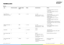
TECHNICAL DATA Outputs Type Maximum quantity Possible configuration Feature • Automated shutdown on overcurrent > 7.5 A ±0.9 A • Output voltage feedback, accuracy is ±4.5 % ±200 mV Digital/PWM half2 bridge output OPHB10A 0 ... 100 % Duty cycle resolution < 0.1 % PWM frequency 5 ... 20000 Hz Digital low side output OPL0A5 0 ... 100 % Duty cycle resolution < 0.1 % PWM frequency 20 ... 1000 Hz • Low-side switch • Output voltage feedback, accuracy is ±4 % ±200 mV • High-side switch • switches the output groups +UB1 to +UB6 • Current up to 12 A Push-pull output Current measurement ±2.3 % ±200 mA...
Open the catalog to page 10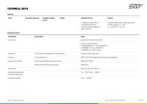
TECHNICAL DATA Outputs Type Maximum quantity Possible configuration • Capacitive load ≤470 µF • Settling time 100 ms Accuracy voltage readback: ±0.9% ±50 mV Programmable output needs derating for output voltages UEXT < 10 V: IMAX = 0.875 / (13.5 - UEXT) A Mechanical data Component 2 LED, dual color (red/green or mixed colors) Die-cast aluminum GORE-TEX™-breathing lter for pressure equalization Variant without M12 Ethernet connector Variant with M12 Ethernet connector Operating temperature, housing temperature Operating altitude Subject to change without notice
Open the catalog to page 11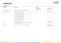
TECHNICAL DATA Power supply Component Range Minimum Value Maximum Value Voltage at +UE ECU supply and +UB power supply Current consumption Power supply +UB1 fully loaded 12 A Power supply +UB2 fully loaded 12 A Power supply +UB3 fully loaded 12 A Power supply +UB4 fully loaded 12 A Power supply +UB5 fully loaded 12 A Power supply +UB6 fully loaded 12 A 4 x low side output OPL4A Standby Sum of input currents at +UE and +UB (UKL15 = 0 V, ignition off) Without external load +UE supply current (UKL15 > UKL15HIGH, no external load) Subject to change without notice
Open the catalog to page 12


