NFF Brake
1 /16Pages

NFF Brake
1 /16Pages
Catalog excerpts
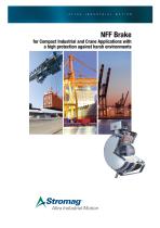
for Compact Industrial and Crane Applications with a high protection against harsh environments
Open the catalog to page 1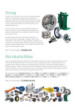
Stromag Founded in 1932, Stromag has grown to become a globally recognized leader in the development and manufacture of innovative power transmission components for industrial drivetrain applications. Stromag engineers utilize the latest design technologies and materials to provide creative, energy-efficient solutions that meet their customer’s most challenging requirements. Stromag’s extensive product range includes flexible couplings, disc brakes, limit switches, an array of hydraulically, pneumatically, and electrically actuated brakes, and a complete line of electric, hydraulic and pneumatic...
Open the catalog to page 2
Applications • Holding- and Working brake variations for industrial applications • Usable for dockside-, harbour and marine crane brake suitable for seawater environment Optional extras • Simple adjustment with adjusting ring • Hand release lever • Tacho / Endcover provision • Terminal box • Micro switch to monitor switching states or wear monitoring • Standstill heater Switching modules • Half wave or full wave • Quick switching units • Built in terminal box • Attached for mounting into the motor terminal box
Open the catalog to page 3
Advantages • Comprehensive range 20 - 10,000 Nm • Simple assembly to motor, no dismantling of brake required • Concentricity through body for tacho fixing • No setting required when changing armature disc and friction disc • Compatibility of consumable spares • Simple maintenance, once only adjustment by shim removal • Positive feel hand release mechanism • Proven reliable design • Sealed inspection holes for air gap or lining wear • Extremely low inertia • High heat dissipation • Free from axial loads when braking and running • Suitable for vertical mounting, please consult Stromag Dessau GmbH •...
Open the catalog to page 4
NFF – Electromagnetic Spring-Applied Brake Designation of individual components 01) Coil body with coil 11) Brake flange 02) Friction disc with friction lining 15) Pinion 10) Armature dise 21) Compression spring Brake operation Brakes should be switched on the DC side. (This will achieve fastest response times). Brakes are fail-safe i.e. Spring-Applied. Power on to release. When the coil is energized, the magnetic flux attracts the armature disc (10) to the coil body, this compresses the springs (21) and releases the friction disc with friction lining (02) and the brake is released. When the...
Open the catalog to page 5
Micro switch Optional availability, Inboard Proving Switch, one common contact, one normally open contact and one normally closed contact. This can be interlocked with motor contactor for parking brake duty, ie. brake release before starting motor. Brake termination Three standard versions: • Flying leads, usually 1 meter long through PG cable gland in coil body. • IP 66 Terminal box, for easy connection and removal, • Versions for AC supply with built-in full wave or half wave rectification inside the terminal box. Emergency hand release lever No setting is required over maximum lining wear,...
Open the catalog to page 6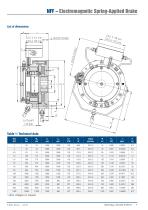
Table 1: Technical data other voltages on request P-8357-SG-A4 02/18
Open the catalog to page 7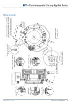
NFF – Electromagnetic Spring-Applied Brake Optional accessories
Open the catalog to page 9
NFF – Electromagnetic Spring-Applied Brake Brake type Brake size Bore diameter with keyway Bore diameter, prebored Nominal voltage With adjusting ring With hand release lever With microswitch With terminal box With rectifier With standstill heater With quick switching unit Figure 1: The diagram shows the time response of an Electromagnetic Spring-Applied Brake as defined by VDE regulations 0580
Open the catalog to page 10
NFF – Electromagnetic Spring-Applied Brake M1 = Switchable torque [Nm] The switchable (dynamic) torque is the torque which can be transmitted by a brake under slip condition depending on the friction coefficient and at working temperature. (M1 = 0, 9MSN) M3 = Synchronization torque [Nm] The synchronization torque is the torque which arises for a short time after finishing the switching process. Mü = Transmissible torque [Nm] The transmissible (static) torque is the max. torque that can be applied to a brake without the risk of slipping. MSN = Switchable nominal torque [Nm] The switchable nominal...
Open the catalog to page 11
NFF – Electromagnetic Spring-Applied Brake Nomenclature AR cm2 Friction surface Heat quantity Specific heat Braking time kJ kJ Steel c = 0, 46 — Cast iron c = 0, 54 — kgK kgK Slipping time Mass moment of inertia J [kgm2] The mass moment of inertia J stated in the formula is the total mass moment of inertia of all the masses to be retarded referred to the brake. Reduction of moments of inertia The reduction of moments of inertia is calculated from the formula n2 J1 = J2 * ( — )2 [kgm2] n1 Moments of inertia of linear masses The equivalent moment of inertia JErs for a linear mass m and a velocity...
Open the catalog to page 12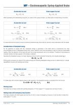
If a brake slips with constant slipping speed under operation, the dissipated energy is calculated from the formula Working brake The brake has to brake a shaft with switching frequency ”X” from speed ”Y” to speed zero and has to hold it. Holding brake with emergency stop function The brake actuates with shaft speed zero and has to hold; in case of emergency, however, it must be able to brake from shaft speed ”Y” to zero.
Open the catalog to page 13
NFF – Electromagnetic Spring-Applied Brake Permissible heat capacity at 1500 rpm Switching operations Figure 2: Heat capacity of series NFF n =1500 rpm **. By known operations and number of operations per hour the brake size can be obtained. Example: W = 100 kJ/operation and z = 10 operations/hour choose the size NFF 25 ** permissible switching operations per switching at other speed ratings on request
Open the catalog to page 14
DRIVING MACHINE
Open the catalog to page 15
Stromag Facilities Europe Germany HansastraBe 120 59425 Unna - Germany +49 (0) 23 03 102 0 Clutches & Brakes, Couplings, Geared Cam Limit Switches, Discs, Wind Brakes Dessauer Str. 10 06844 Dessau-RoBlau - Germany +49 (0) 340 2190 0 Electromagnetic Clutches & Brakes France Avenue de I’Europe 18150 La Guerche sur L’Aubois - France +33 (0)2 48 80 72 72 Industrial Caliper & Drum Brakes Great Britain Ampthill Road Bedford, MK42 9RD - UK +44 (0)1234 350311 Electromagnetic Clutches & Brakes, Industrial Caliper Brakes North America USA 31 Industrial Park Road New Hartford, CT 06057 - USA 860-238-4783 Electromagnetic...
Open the catalog to page 16All STROMAG catalogs and technical brochures
 Carbon Fiber Shaft
1 Page
 Stromag KMS...THC
1 Page
 Stromag Vector Couplings
12 Pages
 4 BZFM Brake
16 Pages
 Clutches and Brakes
8 Pages
 brakes type 600
2 Pages
 Lever Switches, Serie HHEV
9 Pages
 Geared Switches, Serie HGE
24 Pages
 Geared Switches, Serie HEG
10 Pages
 Determination of Clutches
24 Pages
 Spidex®, Dentex®
28 Pages
 Periflex® VN Disc Coupling
36 Pages
 Disc Coupling
36 Pages
 highly-flexible ring couplings
31 Pages
 couplings for Cardan Shaft
34 Pages
 Stromag: safety in motion
20 Pages
 Two-in-one 1
4 Pages
 Two-in-one 2
4 Pages
 Wind Turbine Catalogue
7 Pages
 Hydrid Clutches and Brakes
8 Pages
 High Protection Brake Catalogue
16 Pages
 Flexible Couplings
2 Pages
 Highly-flexible TRI-R Couplings
31 Pages
 Highly-flexible TRI Couplings
33 Pages
 Highly-flexible GE Couplings
28 Pages


Archived catalogs
 Electromagnetic Tooth Clutches
36 Pages
 Driveshaft
44 Pages


- Shaft shaft coupling
- Friction brake
- Pack unit
- Torque coupling
- Transmission coupling
- Electric hydraulic power unit
- Spring brake
- Electromagnetic brake
- Measurement monitoring module
- Friction clutch
- Compact coupling
- Temperature monitoring module
- Motor shaft coupling
- Double-disc coupling
- Compact hydraulic power unit
- Industrial coupling
- Safety brake