

Highly-flexible Periflex® Shaft Couplings

Highly-flexible Periflex® Shaft Couplings
Document Integrity and Content Overview
The document is heavily corrupted or encoded, containing numerous non-standard characters and fragmented text, which prevents direct extraction of detailed technical information. Despite this, the structure suggests it is a technical report or manual related to industrial drive technology, including specifications, procedures, standards, and recommendations.
1. Specifications
This section likely details technical parameters such as numerical values, tolerances, material and component requirements, and performance criteria essential for system reliability. However, exact data and limits cannot be reliably extracted due to document corruption.
2. Procedures
Step-by-step instructions for installation, operation, and maintenance are implied, emphasizing critical control points, safety precautions, and testing methods to ensure system integrity. Specific procedural details remain inaccessible.
3. Standards and Norms
The document references adherence to international and local industry standards, regulatory compliance, documentation, certification, and environmental and safety regulations impacting system design and operation. Precise standards and codes are not clearly identifiable.
4. Recommendations and Best Practices
Guidance on preventive maintenance, operational efficiency, downtime reduction, and personnel training is suggested. Concrete recommendations and schedules are not extractable.
5. Data Tables and Figures
Numerous tables and graphical elements appear to summarize key metrics, procedural flows, and system behavior under various conditions. Due to corruption, these data representations cannot be interpreted or summarized.
Critical Information
The document stresses strict adherence to specified parameters and procedures to ensure safety, compliance, and optimal functionality. Limitations and tolerances are defined to prevent failures, and best practices focus on proactive maintenance and training.
Company and Contact Directory
Separately, the document serves as a comprehensive global contact directory for Stromag AG, a company specializing in drive technology, industrial brakes, clutches, and related mechanical components.
Company Overview
Stromag AG is headquartered in Unna, Germany, with multiple specialized divisions emphasizing safety in motion and offering a broad product range including clutches, brakes, and drive components.
Global Presence
The directory lists detailed contact information for Stromag offices, subsidiaries, and representatives worldwide, covering regions such as Germany, Benelux, France, UK, Italy, Austria, Portugal, Russia, Switzerland, Scandinavia, Spain, Czech Republic, Slovakia, China, India, Japan, South Korea, Taiwan, Australia, South Africa, Brazil, and North America.
Specialized Contacts
Key personnel are identified for product lines and technical expertise areas including switchable clutches and brakes, industrial brakes, end switches, elastic couplings, and compressor applications.
Usage Note
This directory facilitates communication and service across Stromag's global network. For technical inquiries or product support, contacting the appropriate regional office or expert is recommended to access localized expertise.
Catalog excerpts

Hochelastische Periflex®- Highly-flexible Periflex® shaft couplings
Open the catalog to page 1
Periflex® Wellenkupplung Periflex® Shaft-Coupling Alle Angaben uber Periflex® Wellenkupplungen in Druckschrif- ten alteren Datums sind mit dem Erscheinen dieser Druck- schrift nur noch bedingt gultig. Stromag—Produkte entsprechen dem Qualitatsstandard Inhalt Seite Hinweise zur Auswahl der KupplungsgroBe 3-4 Lagerung von gummielastischen Elementen 6 Kennwerte der Periflex® Wellenkupplung 7-10 This catalogue for Stromag Periflex® shaft couplings cancels and replaces all former editions. We reserve the right to modify the dimensions and construc- Stromag products comply with the Quality Standard...
Open the catalog to page 2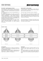
Periflex® Wellenkupplung Periflex® Shaft-Coupling Das PeriflexR-Wellenkupplungs-Konzept Die Stromag Periflex®-Wellenkupplung ist eine hochelastische Gummi-Gewebe-K upplung, besonders geeignet für die VerĆ bindung zweier Wellen in dieselmotorischen und elektrischen Antrieben. Die Baureihe erstreckt sich über den Drehmomentbereich von 25 - 15000 Nm. Die Periflex®-Wellenkupplung kann wegen der besonderen Ausbildung des Wellenreifens extrem große Verlagerungen, bei geringen Rückstellkräften, in jeder Richtung aufnehmen, s. Liste technische Daten, ohne daß sich das als Verschleiß bemerkbar macht....
Open the catalog to page 3
Periflex® Wellenkupplung Periflex® Shaft-Coupling Hinweise für den Konstrukteur Die Kupplungsnaben sowie die Druckringe sind aus Stahl und haben eine Korrosionsschutz-Schicht. Der Wellenreifen ist aus Naturkautschuk mit Gewebeeinlagen, die in radialer oder in diagonaler Ausrichtung eingelegt sind. Durch die Art der GeĆ webeanordnung werden unterschiedliche Drehfedersteifen realisiert. Wellenreifen in flammwidriger, elektrisch isolierender und ölbeĆ ständiger Ausführung sind auf Anfrage lieferbar. Der Wellenreifen ist standardmäßig durch die werkseitig vorgeĆ sehene Trennfuge radial montierbar,...
Open the catalog to page 4
Periflex® Wellenkupplung Periflex® Shaft-Coupling II. Arbeitsmaschinen mit ungleichförmiger Kraftabnahme: mittlere Werkzeugmaschinen mit drehender Hauptbewegung, Turbogebläse (Gasgebläse, Verdichter), Diesel- und Gasmotore, leichte Aufzüge, Kettenförderer, Kranfahrwerke, Sandstrahlgebläse, Textilmaschinen, Becherwerke, Transportanlagen, Ventilatoren, Winden, große Zentrifugalpumpen, Generatoren (Kraftstrom), Hebezeuge bis 120 Schalt./Std. II. Machines with non-uniform power consumption: medium-sized machine tools with rotating main motion, turbo exhausters (gas blowers, compressors), diesel and...
Open the catalog to page 5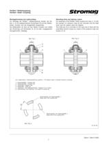
Periflex® Wellenkupplung Periflex® Shaft-Coupling Montagehinweise und Lieferumfang Zur Montage der Periflex R-Wellenkupplung werden die NaĆ ben (1, 2) mit aufgeschobenen Druckringen (3) auf den WellenĆ enden montiert und die Anlagenteile ausgerichtet. Der Wellenreifen (4) wird auf den Naben montiert und mittels der Druckringe und Schrauben (5, 6) mit dem vorgegebenen Anzugsmoment befestigt. Mounting hints and delivery extent For assembly of the Periflex Rshaft coupling the hubs (1, 2) with the pushed-on pressure rings (3) are mounted onto the shaft ends and the system parts are aligned. The shaft...
Open the catalog to page 6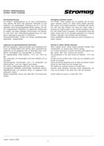
Periflex® Wellenkupplung Periflex® Shaft-Coupling Durchdrehsicherung Die Periflex R-Wellenkupplung ist mit einer DurchdrehsicheĆ rung lieferbar. Bei Bruch des elastischen Elementes ist eine drehstarre und spielbehaftete Verbindung der An- und AbĆ triebsseite durch ineinandergreifende Klauen realisiert. Ein zeitĆ lich eingeschränkter Notbetrieb mit begrenztem Drehmoment ist möglich. Die dabei zulässigen Drehmomente und DrehzahĆ len sind durch eine Drehschwingungsberechnung mit drehĆ starrer Übertragung gesondert zu berechnen. Durchdrehsicherungen werden von einigen KlassifikationsgeĆ sellschaften...
Open the catalog to page 7
Kennwerte der Periflex® Wellenkupplung Characteristics of Periflex® Shaft-Coupling TKN Das Nenndrehmoment der Kupplung kann im gesamten zuläsĆ sigen Drehzahlbereich dauernd übertragen werden. Es darf vom Nenndrehmoment TN der Anlage nicht überschritĆ ten werden TKN > TN TKN The nominal torque of the coupling can be transmitted continuĆ ously over the admissible speed range. The nominal torque TN of the system must not exceed that of the coupling. TKN > TN TKmax Bei PeriflexR-Wellenkupplungen ist das Maximaldrehmoment 3-fach so groß wie das Nenndrehmoment und maßgebend für die Dauerfestigkeit...
Open the catalog to page 8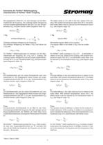
Kennwerte der Periflex® Wellenkupplung Characteristics of Periflex® Shaft-Coupling The stated values of D Kr refer to the max. speed of the couĆ pling. With ambient temperatures higher than 30_C, the admisĆ sible radial offset must be reduced by the temperature factor SϑKr (see diagram page 10). Die angegebenen Werte für D Kr sind bezogen auf die MaxiĆ maldrehzahl der Kupplung. Die zulässige radiale Verlagerung muß bei Umgebungstemperaturen über 30_C um den TemperĆ aturfaktor SϑKr reduziert werden (siehe Diagramm Seite 10). DKr(TU)= DKr SϑKr DKr(TU)= D KW DKr SϑKr D KW winklige Verlagerung angular...
Open the catalog to page 9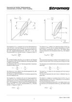
Kennwerte der Periflex® Wellenkupplung Characteristics of Periflex® Shaft-Coupling CTdyn = Tel y = öW T A D A el Tw T el T A el AD öW Dϕ w ϕ ϕ DD8700103-00 Die Angaben für CTdyn beziehen sich auf ein WechseldrehmoĆ ment von 0,25 x TKN, eine Frequenz von 10 Hz und eine UmĆ gebungstemperatur unter 30_C. Die angegebenen Werte müsĆ sen bei Umgebungstemperaturen über 30_ C um den Temperaturfaktor SϑC reduziert werden, s.Diagramm Seite 10. CTdyn SϑC CTdyn(TU)= Die verhältnismäßige Dämpfung ist ein Maß für die Fähigkeit der Kupplung, einen Teil der anfallenden Schwingungsenergie in Wärme umzuwandeln....
Open the catalog to page 10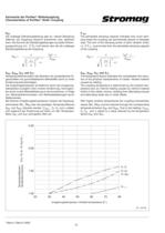
Kennwerte der Periflex® Wellenkupplung Characteristics of Periflex® Shaft-Coupling PKV Die zulässige Dämpfungsleistung gibt an, wieviel Dämpfung (Wärme) die Kupplung dauernd aufnehmen bzw. abführen kann. Die Summe der Dämpfungsleistungen aus jeder SchwinĆ gungsordnung, d.h. S PVi muß kleiner sein als die zulässige Dämpfungsleistung der Kupplung. PKV = Ǹȡ Ȣ π 2π ψ ȣ Ȥ @ 2 P KV The admissible damping capacity indicates how much damĆ ping (heat) the coupling can permanently absorb or dissipate resp. The sum of the damping power of each vibration order, i.e. S P Vi, must be less than the admissible...
Open the catalog to page 11All STROMAG catalogs and technical brochures
 Carbon Fiber Shaft
1 Page
 Stromag KMS...THC
1 Page
 Stromag Vector Couplings
12 Pages
 4 BZFM Brake
16 Pages
 NFF Brake
16 Pages
 Clutches and Brakes
8 Pages
 brakes type 600
2 Pages
 Lever Switches, Serie HHEV
9 Pages
 Geared Switches, Serie HGE
24 Pages
 Geared Switches, Serie HEG
10 Pages
 Determination of Clutches
24 Pages
 Spidex®, Dentex®
28 Pages
 Periflex® VN Disc Coupling
36 Pages
 Disc Coupling
36 Pages
 highly-flexible ring couplings
31 Pages
 couplings for Cardan Shaft
34 Pages
 Stromag: safety in motion
20 Pages
 Two-in-one 1
4 Pages
 Two-in-one 2
4 Pages
 Wind Turbine Catalogue
7 Pages
 Hydrid Clutches and Brakes
8 Pages
 High Protection Brake Catalogue
16 Pages
 Flexible Couplings
2 Pages
 Highly-flexible TRI-R Couplings
31 Pages
 Highly-flexible TRI Couplings
33 Pages
 Highly-flexible GE Couplings
28 Pages


Archived catalogs
 Electromagnetic Tooth Clutches
36 Pages
 Driveshaft
44 Pages


- VirtualExpo Group
- Our Partners
- Recruitment
- Testimonials