

Highly-flexible GE Couplings

Highly-flexible GE Couplings
Document Overview
This technical document relates to the GE coupling system, specifically addressing aspects of pressure or force application (Nachdr-Druck). Although the original text is heavily corrupted, the inferred structure suggests coverage of specifications, operational procedures, performance parameters, standards, and recommendations. Additionally, a separate section provides comprehensive contact information for Stromag AG and its global representatives.
1. Specifications
The document outlines critical technical specifications for the GE coupling, including:
- Mechanical dimensions and material properties essential for compatibility and durability.
- Pressure ratings and operational thresholds to ensure safe and effective use.
- Environmental and safety constraints governing operational limits.
These specifications form the foundation for ensuring consistent performance and compliance with safety standards.
2. Operational Procedures
Step-by-step instructions are provided for installation, adjustment, and maintenance of the coupling system. Key procedural elements include:
- Preparation and setup guidelines to ensure correct assembly.
- Execution protocols detailing timing and sequencing for optimal performance.
- Verification and validation steps to maintain quality control and safety.
Strict adherence to these procedures minimizes risk of failure and prolongs service life.
3. Performance Parameters
The document specifies operational parameters such as:
- Pressure limits and force application ranges defining the coupling’s capabilities.
- Operational tolerances to accommodate variability while maintaining safety.
These parameters guide users in applying the coupling within safe and effective boundaries.
4. Standards and Norms
References to applicable industry standards and regulatory norms are included, emphasizing:
- Compliance with international and local standards for quality and safety.
- Documentation and reporting guidelines to support traceability.
- Quality assurance frameworks to ensure consistent product performance.
5. Recommendations and Best Practices
Recommendations focus on optimizing performance and safety, including:
- Regular maintenance schedules and inspection routines.
- Risk mitigation strategies to prevent operational failures.
- Training and competency requirements for personnel handling the coupling.
Following these best practices supports operational excellence and longevity.
6. Data Tables and Graphical Information
Although the original document references multiple tables and graphs illustrating performance metrics, load capacities, and dimensional tolerances, the corrupted text prevents extraction of specific data. Typically, such visual aids facilitate understanding of process stability, material comparisons, and operational trends.
7. Stromag AG Contact and Regional Representation
The document includes a detailed directory of Stromag AG’s global offices and representatives, covering:
- Headquarters in Unna, Germany, with specialized contacts for clutches, brakes, couplings, and limit switches.
- Regional offices across Europe, Asia, Americas, Oceania, and Africa, each with full contact details.
- Dedicated personnel for technical support and sales inquiries categorized by product expertise.
This directory ensures localized support and clear communication channels worldwide.
Critical Information Highlights
- Strict adherence to specified pressure and force limits is essential to avoid mechanical failure.
- Follow recommended installation, adjustment, and maintenance procedures precisely.
- Operate the coupling within defined environmental and safety parameters.
- Consult detailed specifications for material compatibility and dimensional requirements.
- Utilize the global Stromag contact network for technical support and service.
Conclusion
This document serves as a comprehensive technical guide for the GE coupling system, integrating specifications, procedures, standards, and best practices to ensure quality, safety, and efficiency. Due to text corruption, precise technical data and graphical content could not be extracted. Users are advised to obtain an uncorrupted version for detailed technical reference and to rely on the Stromag global support network for assistance.
Catalog excerpts
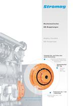
Highly flexible Elementen Aus- und Einbau ohne axiale Verschiebung the elements without axial
Open the catalog to page 1
Alle Angaben uber GE-Kupplungen in Druckschriften alteren Datums sind mit dem Erscheinen dieser Druckschrift nur noch bedingt gultig. Stromag—Produkte entsprechen dem Qualitatsstandard This catalogue for GE-couplings cancels and replaces all former editions. We reserve the right to modify the dimensions and construc- Stromag products comply with the Quality Standard to Hinweise zur Auswahl der KupplungsgroGe 7 Baureihe GET...R mit Tellerflansch 19 Mounting hints and delivery extent 6 Hints for selection of coupling size 7 Series GEF...R with SAE-connection 18 Series GET...R with plate-shaped...
Open the catalog to page 2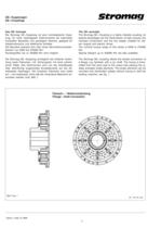
GE-Kupplungen GE-Couplings Das GE-Konzept Die Stromag GE-Kupplung ist eine hochelastische KuppĆ lung, für hohe übertragbare Drehmomente bei besonders kompakter Bauweise und günstigem Gewicht, geeignet für dieselmotorische und elektrische Antriebe. Die Baureihe erstreckt sich über einen NenndrehmomentenĆ bereich von 2000 bis 270000 Nm. Sondergrößen bis zu 450000 Nm sind möglich. The GE-principle The Stromag GE-Coupling is a highly-flexible coupling; its special advantages are the transmission of high torques, the compact construction and the low weight, suitable for dieĆ sel-engine and electric...
Open the catalog to page 3
GE-Kupplungen GE-Couplings Einsatzgebiete Die Stromag GE-Kupplung ist konzipiert für den Einsatz an Kolbenmaschinen. Sie kann mit ihrem Außenteil direkt an das Schwungrad eines Dieselmotors angeflanscht werden. Bei entsprechender Ausführung lassen sich auch zwei Wellen oder zwei Flansche miteinander verbinden. Die Einsatzgebiete sind der Motoren- und Schiffsbau, EisenĆ bahn- und Baumaschinenantriebe, Diesel- und GasaggreĆ gate, Zementmühlen sowie Pumpen und Verdichter. Type of application The Stromag GE-coupling is designed for application with piston engines. With its outer part it can be flanged...
Open the catalog to page 4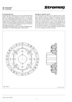
GE-Kupplungen GE-Couplings Durchdrehsicherung Die Stromag GE-Kupplung ist mit einer Durchdrehsicherung lieferbar. Bei Bruch der elastischen Elemente ist eine drehĆ starre und spielbehaftete Verbindung der An- und AbtriebsĆ seite durch ineinandergreifende Klauen realisiert. Ein zeitlich eingeschränkter Notbetrieb mit begrenztem Drehmoment ist möglich. Die dabei zulässigen Drehmomente und Drehzahlen sind durch eine Drehschwingungsberechnung mit drehstarrer Übertragung gesondert zu berechnen. Durchdrehsicherungen werden von einigen KlassifikationsgeĆ sellschaften für Schiffshauptantriebe vorgeschrieben....
Open the catalog to page 5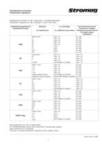
Klassifikationsvorschriften Classification regulations Klassifikationsvorschriften für GE-Kupplungen in Schiffshauptantrieben Classification regulations for GE-couplings in marine main drives Eisklasse TN-Zuschläge Ice classification TN-additional torque factor Durchdrehsicherung bei Einmotoren-Anlagen Emergency operation device for single-engine installations ABS keine /none C IC IB IA B A IAA AA nein / no nein / no nein / no nein / no nein / no 13 % 26 % 33 % 40 % ja / yes ja / yes ja / yes ja / yes ja / yes ja / yes ja / yes ja / yes ja / yes BV keine/none III II I I super nein / no nein /...
Open the catalog to page 6
GE-Kupplungen GE-Couplings Montagehinweise und Lieferumfang Die Stromag GE-Kupplung kann mit ihrem Außenteil (2, 3) direkt an das Schwungrad eines Motors angeschraubt werĆ den, von wo aus das zu übertragende Drehmoment über sternförmig angeordnete Gummielemente (4) und die Nabe (1) auf eine angeschlossene Maschine übertragen wird. 2 Mounting hints and delivery extent The Stromag GE-coupling can be screwed directly to the flywheel of an engine by its outer part (2, 3); from that flywĆ heel the torque is transmitted to a connected machine pasĆ sing the radially arranged rubber elements (4) and...
Open the catalog to page 7
GE-Kupplungen GE-Couplings Hinweise zur Auswahl der Kupplungsgröße Die Stromag GE-Kupplung weist eine progressive VerdrehĆ kennlinie auf (Bild 3). Hints for selection of coupling size The Stromag GE-coupling has a progressive torsional chaĆ racteristic curve (fig. 3). GE-Kupplung Gr. 700 / GE-Coupling size 700 Drehmoment Torque T 25000 Nm 20000 15000 10000 T KN 5000 10 20 15 5 5000 TKN 10000 0 5 10 15° 20 Verdrehwinkel Torsion Angle 15000 20000 25000 Bild / Fig. 3 Es liegen die statischen und dynamischen Kennwerte vor. Mit ihrer Hilfe ist es möglich, die geeignete Kupplungsgröße für den vorliegenden...
Open the catalog to page 8
Die Kennwerte der GE-Kupplung Characteristics of the GE-coupling TKN Das Nenndrehmoment der Kupplung kann im gesamten zuĆ lässigen Drehzahlbereich dauernd übertragen werden. Es darf vom Nenndrehmoment TN der Anlage nicht überschritten werden. TKN The nominal torque of the coupling can be transmitted contiĆ nuously over the admissible speed-range. The nominal torĆ que TN of the installation must not exceed that one of the coupling. TKN > TN TKmax Bei Stromag GE-Kupplungen ist das Maximaldrehmoment 3-fach so groß wie das Nenndrehmoment und maßgebend für die Dauerfestigkeit der Kupplungen. TKN >...
Open the catalog to page 9
Die Kennwerte der GE-Kupplung Characteristics of the GE-coupling Die bei der Stromag GE-Kupplung angegebenen Werte für D Kr beziehen sich auf Drehzahlen der Kupplungswelle bis zu 600 min-1. Die Umrechnung auf eine andere Drehzahl erfolgt nach der Beziehung 600 min-1 DKr(n)= n SDK The conversion to other speeds is made by the equation 600 min-1 DKr(n)= r Die zulässige radiale Verlagerung muß bei UmgebungstemĆ peraturen über 30_C um den Temperaturfaktor SϑKr reduziert werden. DKr(TU)= The value of D Kr stated for the Stromag GE-coupling refers to coupling shaft speeds up to 600 rpm. DKr SϑKr D...
Open the catalog to page 10
Die Kennwerte der GE-Kupplung Characteristics of the GE-coupling Bei GE-Kupplungen steigt der CTdyn-Wert progressiv über dem Kupplungsdrehmoment an. Er verändert sich jedoch mit der Größe der Amplitude, deren Frequenz und der ElemenĆ ten-Temperatur. Die Angaben für CTdyn beziehen sich auf ein WechseldrehĆ moment von 0,2 x TKN,, eine Frequenz von 10 Hz und eine Umgebungstemperatur von 30_C. Die angegebenen Werte müssen bei Umgebungtemperaturen über 30_ C um den Temperaturfaktor SϑC korrigiert werden. CTdyn(TU)= For GE-couplings the value CTdyn rises progressively over the nominal torque. It changes,...
Open the catalog to page 11All STROMAG catalogs and technical brochures
 Carbon Fiber Shaft
1 Page
 Stromag KMS...THC
1 Page
 Stromag Vector Couplings
12 Pages
 4 BZFM Brake
16 Pages
 NFF Brake
16 Pages
 Clutches and Brakes
8 Pages
 brakes type 600
2 Pages
 Lever Switches, Serie HHEV
9 Pages
 Geared Switches, Serie HGE
24 Pages
 Geared Switches, Serie HEG
10 Pages
 Determination of Clutches
24 Pages
 Spidex®, Dentex®
28 Pages
 Periflex® VN Disc Coupling
36 Pages
 Disc Coupling
36 Pages
 highly-flexible ring couplings
31 Pages
 couplings for Cardan Shaft
34 Pages
 Stromag: safety in motion
20 Pages
 Two-in-one 1
4 Pages
 Two-in-one 2
4 Pages
 Wind Turbine Catalogue
7 Pages
 Hydrid Clutches and Brakes
8 Pages
 High Protection Brake Catalogue
16 Pages
 Flexible Couplings
2 Pages
 Highly-flexible TRI-R Couplings
31 Pages
 Highly-flexible TRI Couplings
33 Pages


Archived catalogs
 Electromagnetic Tooth Clutches
36 Pages
 Driveshaft
44 Pages


- Shaft shaft coupling
- Friction brake
- Pack unit
- Torque coupling
- Spring brake
- Transmission coupling
- Disc brake
- Electric hydraulic power unit
- Electromagnetic brake
- Measurement monitoring module
- Friction clutch
- Compact coupling
- Temperature monitoring module
- Motor shaft coupling
- Double-disc coupling
- Compact hydraulic power unit
- Industrial coupling
- Electromagnetic clutch