
Catalog excerpts
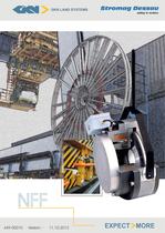
<4 MM GKN LAND SYSTEMS SfTOfff Cfflf DBSSCIU B^^fc^W safety in motion EXPECT MORE
Open the catalog to page 1
Electromagnetic Spring-Applied Brake ■/ Holding- and Working brake variations for industrial Application ■/ Usable for dockside-, harbour and marine crane brake suitable for seawater environment Standard Features Coil Body with coil : Thermal class 155, nitrocarburated and postoxidated Outer Body : Manufactured in sea water proof aluminium with large inspection holes Armature Plate : Special protection: nitrocarburated and postoxidated Brake Flange : Special protection: nitrocarburated and postoxidated Friction Lining : Low wear rate with low torque fade over a high range of temperature....
Open the catalog to page 2
Electromagnetic Spring-Applied Brake ■/ Simple assembly to motor, no dismantling of brake required. ■/ Concentricity through body for tacho fixing ■/ No setting required when changing armature disc and friction disc ■/ Compatibility of consumable spares ■/ Simple maintenance, once only adjustment by shim removal ■/ Positive feel hand release mechanism ■/ Proven reliable design ■/ Sealed inspection holes for air gap or lining wear ■/ High heat dissipation ■/ Free from axial loads when braking and running ■/ Suitable for vertical mounting, please consult GKN Stromag Dessau GmbH ■/ Many...
Open the catalog to page 3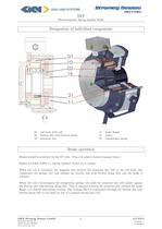
Electromagnetic Spring-Applied Brake Designation of individual components 01 coil body with coil 11 brake flange 02 friction disc with friction lining 15 pinion 10 armature disc 21 compression spring Brake operation Brakes should be switched on the DC side. (This will achieve fastest response times). Brakes are FAIL SAFE i.e. Spring Applied. Power on to release. When the coil is energized, the magnetic flux attracts the armature disc (10) to the coil body, this compresses the springs (21) and releases the friction disc with friction lining (02) and the brake is When the coil is de-energized...
Open the catalog to page 4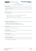
Electromagnetic Spring-Applied Brake Optional availability, Inboard Proving Switch, one common contact, one normally open contact and one normally closed contact. This can be interlocked with motor contactor for parking brake duty, ie. brake release before starting Three standard versions: • Flying leads, usually 1 meter long through PG Cable Gland in coil body. • IP66 Terminal box, for easy connection and removal, • Versions for AC supply with built-in full wave or half wave rectification inside the Terminal ■/ Emergency hand release lever No setting is required over maximum lining wear,...
Open the catalog to page 5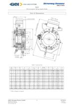
Electromagnetic Spring-Applied Brake Table 1: technical data * other voltages on request GKN Stromag Dessau GmbH 5 449-00010 Dessauer Strafie 10 Version: -
Open the catalog to page 6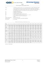
Electromagnetic Spring-Applied Brake thermal class switchable nominal torque at lm/s frictional speed to DIN VDE 0580 (applies to dry operation with an oil- and grease-free friction lining after running-in) transmissible static nominal torque without slip, to DIN VDE 0580 (applies to dry operation with an oil- and grease-free friction lining after running-in) maximum idling speed admissible switching speed nominal braking capacity (S4-40 % I.O.) switch work per switching operation for z = 1 — 5/i_1 mass moment of inertia of rotating parts Table 2: list of dimensions (all dimensions in mm)...
Open the catalog to page 7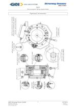
Electromagnetic Spring-Applied Brake Optional Accessories GKN Stromag Dessau GmbH 7 449-00010 Dessauer Strafie 10 Version: -
Open the catalog to page 8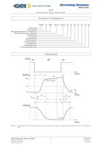
Electromagnetic Spring-Applied Brake Figure 1: The diagram shows the time response of an electromagnetic spring - applied brake as defined by the VDE regulations GKN Stromag Dessau GmbH 8 449-00010 Dessauer StraBe 10 Version: -
Open the catalog to page 9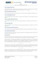
NFF Electromagnetic Spring-Applied Brake M1 = switchable torque [N m] The switchable (dynamic) torque is the torque which can be transmitted by a brake under slip condition depending on the friction coecient and at working temperature. (M1 = 0, 9MSN ) M3 = synchronization torque [N m] The synchronization torque is the torque which arises for a short time after nishing the switching process . MU = transmissible torque [N m] ¨ The transmissible (static) torque is the max. torque that can be applied to a brake without the risk of slipping. MSN = switchable nominal torque [N m] The switchable...
Open the catalog to page 10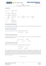
Electromagnetic Spring-Applied Brake Friction surface Heat quantity Watt(W) Heat per hour - Specific heat Mass moment of inertia J [kgm2] The mass moment of inertia J stated in the formula is the total mass moment of inertia of all the masses to be retarded referred to the brake. Reduction of moments of inertia The reduction of moments of inertia is calculated from the formula Moments of inertia of linear masses The equivalent moment of inertia JETS for a linear mass m and a velocity v referred to the brake speed n is calculated from the formula Torque considerations for the brake The mean...
Open the catalog to page 11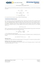
NFF Electromagnetic Spring-Applied Brake When expressing the decelerating torque MA by means of the pulse principle, we obtain after corresponding conversion MA = J ∗ MSN = tA = dω dt [N m] J ∗n ± ML 9, 55 ∗ ta [N m] J ∗n 9, 55 ∗ (MSN ± ML ) [s] It is assumed that the dynamic torque is achieved instantaneously. Considerations of dissipated energy For all operations at speed with slip, dissipated energy is generated in the brake which is transformed into heat. The admissible amount of dissipated energy resp. power capacity must not be exceeded in order to avoid any inadmissible heating....
Open the catalog to page 12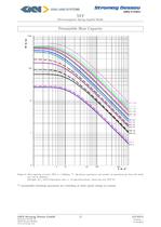
Electromagnetic Spring-Applied Brake Permissible Heat Capacity Figure 2: Heat capacity of series NFF n = 1500rpm **. By known operations and number of operations per hour the brake Example: Q = 100 k J/operation and z = 10 operations/hour choose the size NFF 25 ** permissible switching operations per switching at other speed ratings on request GKN Stromag Dessau GmbH 12 449-00010 Dessauer StraBe 10 Version: -
Open the catalog to page 13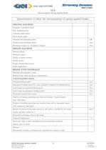
Electromagnetic Spring-Applied Brake Questionnaire to allow the determination of spring applied brakes GKN Stromag Dessau GmbH 13 449-00010 Dessauer StraBe 10 Version: -
Open the catalog to page 14All STROMAG catalogs and technical brochures
-
Carbon Fiber Shaft
1 Pages
-
Stromag KMS...THC
1 Pages
-
Stromag Vector Couplings
12 Pages
-
4 BZFM Brake
16 Pages
-
NFF Brake
16 Pages
-
Clutches and Brakes
8 Pages
-
brakes type 600
2 Pages
-
Lever Switches, Serie HHEV
9 Pages
-
Geared Switches, Serie HGE
24 Pages
-
Geared Switches, Serie HEG
10 Pages
-
Determination of Clutches
24 Pages
-
Spidex®, Dentex®
28 Pages
-
Periflex® VN Disc Coupling
36 Pages
-
Disc Coupling
36 Pages
-
highly-flexible ring couplings
31 Pages
-
couplings for Cardan Shaft
34 Pages
-
Stromag: safety in motion
20 Pages
-
Two-in-one 1
4 Pages
-
Two-in-one 2
4 Pages
-
Wind Turbine Catalogue
7 Pages
-
Hydrid Clutches and Brakes
8 Pages
-
High Protection Brake Catalogue
16 Pages
-
Flexible Couplings
2 Pages
-
Highly-flexible TRI-R Couplings
31 Pages
-
Highly-flexible TRI Couplings
33 Pages
-
Highly-flexible GE Couplings
28 Pages
Archived catalogs
-
Electromagnetic Tooth Clutches
36 Pages
-
Driveshaft
44 Pages


