

Driveshaft

Driveshaft
The document explains the universal joint, also known as the Cardan or Hooke’s Joint, which consists of a journal and four bearings used to transmit torque between inclined shafts. It highlights the Cardan error, which causes non-uniform rotation, and suggests using a second joint in phase to compensate for this error.
Driveshaft selection is based on service life requirements, considering factors such as torque, joint angles, joint life, application data (shocks, vibrations), and critical speed. A step-by-step guide is provided for selecting the correct driveshaft, including calculating torque, determining angle and life factors, and checking maximum torque against short duration torque ratings.
The service factor (K) is determined based on load conditions and the type of driven machine, ranging from 1.2 for continuous loads to 6 for extreme shock loads.
Maximum torque is calculated using the formula Tmax = T x K, where T is the torque and K is the service factor. This value should not exceed the short duration torque rating of the selected driveshaft series.
The document outlines the relationship between angle and speed for different joint sizes, emphasizing that angle and speed must intersect below the series line. Recommendations are provided for deflection angles greater than 5°.
Critical speed is discussed in relation to speed and length, with the maximum working speed set at 70% of the critical speed for safety. A graph is provided for determining maximum working speed based on standard tube dimensions.
Sections on installation, inspection, maintenance, bolting, lubrication, and re-greasing intervals are included to ensure proper operation and longevity of the driveshafts.
The document provides a formula for calculating the critical speed of driveshafts with non-standard tube dimensions. The critical speed (ncrit) is calculated using the formula: ncrit = 1.22 x 10⁷ x (D2 + d2) / L2, where D is the outside diameter, d is the inside diameter, and L is the length of the driveshaft, all in centimeters. The maximum working speed should be limited to 70% of the calculated critical speed.
The critical length (Lcrit) can be calculated using the formula: Lcrit = 1.22 x 10⁷ x (D2 + d2) / n, where n is the critical speed.
Detailed tables list specifications for various types of driveshafts, categorized by duty (light, medium, heavy, extra-heavy) and type (telescopic, short coupled, midship). Each entry includes torque (Tsd), series, part number, maximum angle, dimensions, and weight. Dimensions are provided in millimeters, and torque is given in Newton-meters (Nm).
Tables specify available flange sizes and note that holes in SAE flanges are not equi-spaced. PCD (Pitch Circle Diameter) is provided for each flange type.
The document notes that the listed driveshafts are standard assemblies, but shorter coupled driveshafts can be manufactured using special parts. For more information, contact the technical sales department.
Detailed specifications for various types of driveshafts, including telescopic and short-coupled driveshafts, are provided. Key parameters include torque (Tsd in Nm), series, part number, maximum angle, dimensions (A, B, C, PCD, d), dowel specifications, compressed length (Lz), extension (La), and weight. All dimensions are in millimeters, and shaft weight is in kilograms. The driveshafts are standard assemblies, but shorter versions can be manufactured upon request.
Details are provided for DIN flanges, including outer diameter (OD), pitch circle diameter (PCD), and other dimensions. SAE companion flanges are available upon request.
Specifications for universal joints are given, including series, part number, cup diameter (A), and lengths (B, C).
Stromag driveshafts are delivered as complete units ready for installation. They are balanced according to VDI 2060 and ISO 1940/41 standards and have a primer coat. Suitable for temperatures between -35°C and +60°C, they require lithium-based grease with EP additives before initial operation. Transportation should be horizontal to prevent damage, and nylon ropes are recommended for handling.
Check for transit damage before installation. Driveshafts stored for long periods should be regreased. Ensure flanges are free from corrosion agents, paint, grease, and dirt. Use the correct size nuts and bolts, tightened crosswise to the recommended torque. Protect rotating shafts and joints with guards to prevent physical contact.
Regular inspection is recommended, at least annually. Check flange bolts for tightness and adhere to the lubrication schedule. Inspect for unusual noises or vibrations and repair any damage. Ensure bolts are tightened to the specified torque, and use only lightly oiled bolts without MOS2 additives.
The document outlines the maintenance and lubrication procedures for driveshafts used in industrial plants. The maximum lubrication pressure is 15 bar, and there are three areas to lubricate: the universal joints and the splined sleeve. Regular inspections are recommended, ideally coordinated with other maintenance work, but at least annually.
Regular inspections should include checking flange bolts for tightness and retightening them with the prescribed torque. Nuts and screws should be evenly tightened crosswise. Lubrications containing MOS2 additives must not be used. The lubrication schedule should be maintained, and any visible or tangible backlash in the driveshaft should be repaired. Unusual noise, vibration, or abnormal behavior should also be addressed.
Inspections must include checking bolts for prescribed tightening torques. Screws should be slightly oiled, and lubrications with MOS2 additives should be avoided.
Driveshafts should be greased with lithium-based grease with EP additives. Grease nipples must be cleaned before greasing. The lubrication of the universal joint should ensure fresh grease from all four bearing seals, and the splined sleeve should be lubricated with the driveshaft fully compressed to prevent excessive axial force.
Recommended regreasing intervals vary based on vehicle type and usage conditions. For commercial vehicles and buses, intervals are every 10,000 km or 3 months. For vehicles used on and off-road, intervals are every 5,000 km or 2 months. For construction vehicles and similar, intervals are every 2,500 km or 1 month. Driveshafts in industrial plants under normal conditions should be lubricated every three months, but adverse conditions may require shorter intervals.
The document provides contact details for various Stromag representatives and subsidiaries across Europe, Asia, Australia, Africa, Latin America, and North America, including phone numbers, fax numbers, and email addresses for each location.
Catalog excerpts
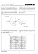
Das Kreuzgelenk, auch als Kardangelenk oder Hookes Gelenkbezeichnet, besteht aus einem Zapfenkreuz (Drehkreuz) undvier Lagern. Das Kreuzgelenk Ҽbertrgt das Drehmoment voneiner geneigten Welle auf eine andere. Diese Konstruktion wirdschon seit ber 700 Jahren angewandt.Die gleichf伶rmige Drehung ϖ 1 of a single Universal Joint deflectedat a certain angle β will result in a non−uniform rotation of theoutput side of the joint. ϖ 1 eines einzelnen Kardangelenks,die an einem gegebenen Winkel β ausgelenkt wird, erzeugt ei−ne nicht gleichfrmige Drehung der Ausgangsseite des Ge梈lenks. The Universal Joint...
Open the catalog to page 4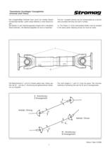
Die unregelmige Drehzahl kann durch ein zweites Gelenkkompensiert werden, sofern beide Gelenke in einer Ebene lie䟢Ȓgen.Die Gabeln (1) der Verbindungswelle mssen sich in derselbenEbene befinden. Die Markierungspfeile (2) sind zu beachten.The non좈constant velocity can be compensated by a secondJoint provided that they are both in phase.i.e. The Yokes (1) of the intermediate Shafts must be situatedin the same plane. Marking arrows (2) must be noted. Die Gelenkwinkel Ҏ 1 und Ҏ 2 mҼssen gleich sein. Hierzu ste−hen die W− und die Z−Anordnung als gebruchliche Verfah䢈ren zur Auswahl.The Joint angles...
Open the catalog to page 5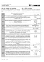
Die Auswahl der richtigen Gelenkwelle fr einen bestimmtenEinsatzbereich ist abh伤ngig von der erforderlichen Betriebsle− bensdauer, die sich wiederum aus den nachstehenden Kriterienergibt. Selection of the correct Universal Drive shaft for an applicationis dependent on the service life required, this is based on the following criteria Schritt / Step1 Drehmoment gem der Formel berechnen / Calculate torque using formula T= 9545 x P n > Winkelfaktor (FA) und Lebensdauer䟢ȒFaktor (FL) aus den Anforderungen an Lebens−dauer und Winkel in Verbindung mit den Abbildungen ermitteln. /Use life and angle requirements...
Open the catalog to page 6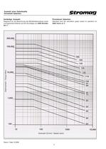
Diagramm fr die Berechnung der Betriebslebensdauer einesnormgerechten Gelenks auf der Grundlage von Standard Joint life calculation graph vased on operation for 5000 Stundenbei 3 估 5000 hours at 3 . . > Drehmoment / Torque (Nm)
Open the catalog to page 8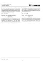
Maximum Torque Shock and vibrations are dependant on the application. These must be taken into consideration by using Service Factor Kwhen calculating the maximum torque.Maximum torque is cal−culated by using the formula: Der Umfang, in dem Ste und Vibrationen auftreten, ist ab柢Ȓhngig vom Einsatzbereich. Diese Aspekte mssen beim Be伢Ȓrechnen des maximalen Drehmoments bercksichtigt werden,und zwar in Form des des Service좈Faktors K. Formel zur BeҢȒrechnung des maximalen Drehmoments: Tmax = T x K (Nm) Where:Tmax= maximum torqueT= TorqueK= Service factorMaximum torque calculated by this method should...
Open the catalog to page 10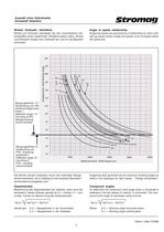
Winkel und Drehzahl unterliegen bei den verschiedenen Ge䢈lenkgrҶen einem bestimmten Verhߤltnis (siehe unten). Winkel und Drehzahl mssen sich unterhalb der Linie fr die Baureiheschneiden. Angle and speed are governed by a relationship for each Jointsize as shown below. Angle and speed must increased below the series line. > Arbeitswinkel / Joint Working Angle Beugungswinkel >5켰:Verwendung von AFL(Anflanschlager) emp−fohlen./ Deflection angle >5:mounting of AFL (flanged bearing recommended)Beugungswinkel Тɤ 5:Verwendung vonPCSТȒKupplungempfohlen./ Deflection angle ≤ 5:mounting ofPCSТȒcouplingrecommended...
Open the catalog to page 11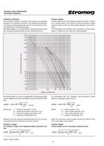
Das Verhltnis zwischen Drehzahl und Lnge ist zu beachtenbez䤼glich der kritischen Drehzahl. Die maximale Arbeitsdreh−zahl liegt aus Sicherheitsgrnden bei 70 % der kritischen Dreh좈zahl gemҤ den Rohrabmessungen.Bei Gelenkwellen mit normgerechten Rohrabmessungen geht die maximale Arbeitsdrehzahl aus der Abbildung hervor. Another relationship is that between speed and length, referredto as critical speed. The maximum working speed for safetyreasons is taken at 70% of critical speed relevant to tube dimenߢȒsions.For Driveshafts with standard tube dimensions use the graph shown to determine the maximum...
Open the catalog to page 12
Tabelle / Table Einsatzbereich/Range Gre/Size Drehmoment/Torque verf柼gbare Flanschgren/Flange Sizes Available verf柼gbare Typen/Types Available Seite/Dimensions g y SAE DIN Page Page L e i chtlast − 2536 4555 57099020503120 11401310 14101510 90100 120150 A, Y , M 12 to 14 betr i eb /Li ght Dut y M i ttellast − 6575859597 40008000100001750019000 1510160017001800180018001900 120 150150165180150180180225180225250 A, Y , M , B 15 to 22 betr i eb / Med i um Dut y Schwerlast − 105115 125135145155165 18000 25000 37000520007200094000136000 225 250 285315350390435 A, Y , B 23 to 25 betr i eb /H ea vy Dut...
Open the catalog to page 13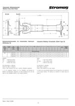
Dreh 좈 GrҶe/Series TeileNummer/PartNumber Max.Beuge A B B1 C PCD No./ d E F G H I J M Lz(Min.) Gewicht/Weight(Lz Min.) moment/TorqueTsd(Nm) ߢȒ winkel/Max.Angle SAE Flansch/Flange 8000 75 75B707004 25 203 1 . 8 1 . 5 196 . 85 184 . 15 8 / 9 . 5 72 10 155 90 70 175 190 445 28 75B717004 35 а 203 1 . 8 1 . 5 196 . 85 184 . 15 8 / 9 . 5 85 10 155 90 70 175 190 458 28 75B818004 35 203 1 . 8 1 . 5 196 . 85 184 . 15 12 / 11 . 1 85 10 155 90 70 175 190 458 28 HIN W EI S : T E: PCD= Te i lkre i sdurchmesserTsd= PCD= P i tch C i rcle D i ameterTsd Sp i t z endrehmoment ( N m)= Short durat i on torque Lz...
Open the catalog to page 24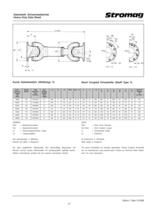
Dreh − Gre/Series TeileNummer/PartNumber Max.Beuge A B C PCD No./ d E F G LzA LaA LzB LaB LzC LaC Gewicht/WeightB(Lz Min.) moment/TorqueTsd(Nm) 柢Ȓ winkel/Max.Angle 18000 105 105Y2250 15 225 5 140 196 8 / 16 108 15 225 650 75 600 45 550 40 90 25000 115 115Y2500 15 а 250 6 140 218 8 / 18 135 18 225 840 90 780 50 710 40 118 37000 125 125Y2850 15 385 7 175 245 8 / 20 135 20 285 855 100 795 60 735 60 156 52000 135 135Y3150 15 а 315 7 175 280 8 / 22 150 22 315 1025 120 950 70 880 85 230 72000 145 145Y3500 15 350 8 220 310 10 / 22 170 25 350 1160 135 1070 90 980 70 333 94000 155 155Y3900 15 а 390 8...
Open the catalog to page 27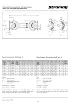
Dreh 좈 GrҶe/Series TeileNummer/PartNumber Max.Beuge A B C PCD No./ Ds No./ E F G LzA LaA LzB LaB LzC LaC Gewicht/WeightB(Lz Min.) moment/TorqueTsd(Nm) ߢȒ d dSpann winkel/Max.Angle − hlsen/Dowel 33000 106 106Y2250 15 225 5 140 196 8 / 16 192 4 / 21 108 15 225 650 75 600 45 550 40 72 40000 116 115Y2500 15 찰 250 6 140 218 8 / 18 214 4 / 25 135 18 225 840 90 780 50 710 40 118 47000 126 126Y2850 15 285 7 175 245 8 / 20 240 4 / 28 135 20 285 855 100 795 60 735 60 156 70000 136 136Y3150 15 а 315 7 175 280 8 / 22 270 4 / 30 150 22 315 1025 120 950 70 880 85 230 102000 146 146Y3500 15 350 8 220 310 10...
Open the catalog to page 30All STROMAG catalogs and technical brochures
 Carbon Fiber Shaft
1 Page
 Stromag KMS...THC
1 Page
 Stromag Vector Couplings
12 Pages
 4 BZFM Brake
16 Pages
 NFF Brake
16 Pages
 Clutches and Brakes
8 Pages
 brakes type 600
2 Pages
 Lever Switches, Serie HHEV
9 Pages
 Geared Switches, Serie HGE
24 Pages
 Geared Switches, Serie HEG
10 Pages
 Determination of Clutches
24 Pages
 Spidex®, Dentex®
28 Pages
 Periflex® VN Disc Coupling
36 Pages
 Disc Coupling
36 Pages
 highly-flexible ring couplings
31 Pages
 couplings for Cardan Shaft
34 Pages
 Stromag: safety in motion
20 Pages
 Two-in-one 1
4 Pages
 Two-in-one 2
4 Pages
 Wind Turbine Catalogue
7 Pages
 Hydrid Clutches and Brakes
8 Pages
 High Protection Brake Catalogue
16 Pages
 Flexible Couplings
2 Pages
 Highly-flexible TRI-R Couplings
31 Pages
 Highly-flexible TRI Couplings
33 Pages
 Highly-flexible GE Couplings
28 Pages


Archived catalogs
 Electromagnetic Tooth Clutches
36 Pages


- Flexible coupling
- Shaft shaft coupling
- Friction brake
- Pack unit
- Torque coupling
- Limit switch
- Spring brake
- Transmission coupling
- Disc brake
- Electric hydraulic power unit
- Electromagnetic brake
- Measurement monitoring module
- Friction clutch
- Compact coupling
- Temperature monitoring module
- Motor shaft coupling
- Double-disc coupling
- Compact hydraulic power unit
- Industrial coupling
- Electromagnetic clutch