
- Catalogs
- STRACK NORMALIEN
- Roller slide units and lateral slide units

Roller slide units and lateral slide units

Roller slide units and lateral slide units
Overview
This document provides detailed technical specifications, dimensional data, load capacities, and operational parameters for various types of roller slide units and lateral slide units with cam systems manufactured by STRACK NORMA GmbH & Co. KG. The content is presented in German, English, and French, targeting international users.
1. Product Types and Descriptions
- Lateral Slide Units with Cam System (Seitenschiebereinheiten mit Nockensystem): These units are designed for lateral movement with integrated cam mechanisms to control motion. Types include SN 5610, SN 5615, and SN 5620 series.
- Roller Slide Units (Rollenschiebereinheiten): These units utilize rollers for smooth sliding action, available in various sizes (e.g., 2000, 3000, 5000, 15000).
2. Technical Specifications
2.1 Dimensions and Mounting
Each unit type is provided with detailed dimensional tables including parameters such as length (L, L1-L11), width (B, B1-B4), height (H, H1-H3), diameters (D1-D5), radii (r), and mounting hole specifications (e.g., M6, M8, M10, M12). Variants with and without mounting plates (P1 and P0) are available.
2.2 Working Stroke and Stroke Types
Working stroke (Hub) values vary by model and type, with typical strokes ranging from 9 mm to over 100 mm depending on the unit size and application. Stroke is denoted by 'S' or 'SP' in the tables.
2.3 Maximum Punching Force and Load Capacities
Maximum punching forces are specified in daN (decanewtons), with values ranging from 750 daN up to 15,000 daN depending on the unit type and size. Gas springs with specified forces (e.g., 200 daN, 400 daN, 600 daN) are used to assist operation.
2.4 Maximum Inclination
Maximum permissible inclination angles vary by unit type, typically between 20° and 50°, with some models allowing up to 45° or 50°.
2.5 Materials and Hardness
Cutting punches are made from high-speed steel (HSS, material 1.3343) with hardness approximately 62 ±2 HRC.
3. Functional Features
- Anti-spinning Device: Units include anti-rotation features to prevent twisting during operation.
- Forced Return: Forced return mechanisms are available on demand to ensure reliable retraction of the slide units.
4. Load Diagrams and FEM Analysis
Load diagrams illustrate the maximum permissible horizontal and vertical loads as a function of punch position (B and H coordinates in mm). These diagrams are based on FEM (Finite Element Method) analysis to ensure structural integrity under operational stresses.
Key observations from load diagrams:
- Load capacity decreases as the punch position moves away from the center (0 mm).
- Vertical loads can exceed horizontal loads, with maximum vertical forces reaching up to 150,000 N for the largest units.
- Load percentages relative to maximum load are provided to assist in design and safety considerations.
5. Ordering and Customization
Customers are advised to specify stroke length and other parameters when ordering. Options such as gas spring force, forced return, and mounting plate inclusion are customizable.
Delivery without mounting plates is available upon request.
6. Contact and Manufacturer Information
STRACK NORMA GmbH & Co. KG provides contact details including telephone and fax numbers, and the website www.strack.de for further inquiries and support.
Summary of Critical Parameters
| Unit Type | Max Punching Force (daN) | Working Stroke (mm) | Max Inclination (°) | Gas Spring Force (daN) |
|---|---|---|---|---|
| SN 5610-750 | 750 | 9 | 20-35 | 200 (±20) |
| SN 5610-3500 to 10000 | 3500 - 10000 | 25 - 63 | 20-25 | 200 - 600 (±20) |
| SN 5615-3500 to 10000 | 3500 - 10000 | 25 - 63 | 25-45 | 200 - 600 (±20) |
| SN 5620 Roller Units (2000 - 15000) | 2000 - 15000 | 50 - 100 | 30-50 | 140 - 400 (±20) |
Best Practices and Recommendations
- Specify exact stroke length and gas spring force when ordering to ensure compatibility with application requirements.
- Consider maximum inclination limits to avoid operational issues.
- Use load diagrams to verify that punch positions and applied forces remain within safe limits.
- Request forced return options if slide retraction is critical for the application.
Conclusion
This document serves as a comprehensive technical reference for selecting and specifying roller and lateral slide units with cam systems. It includes essential mechanical dimensions, load capacities, and operational parameters to support design, ordering, and safe use in industrial applications.
Catalog excerpts
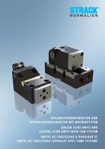
ROLLENSCHIEBEREINHEITEN UND SEITENSCHIEBEREINHEITEN MIT NOCKENSYSTEM ROLLER SLIDE UNITS AND LATERAL SLIDE UNITS WITH CAM SYSTEM UNITES DE COULISSEAU A ROULEAUX ET UNITES DE COULISSEAU LATERALES AVEC CAME SYSTEME
Open the catalog to page 1
k. Schiebere'mheiten / Slide units / Unites de coulisseau
Open the catalog to page 2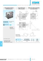
Schiebereinheiten / Slide units / Unités de coulisseau Seitenschiebereinheiten mit Nockensystem Lateral slide units with cam system www.strack.de Unités de coulisseau latérales avec came système Treiber Pusher Poussoir Ø11 Sp Ø6,6 51,6 21 3 18 ±0,05 45 S Ø6 H7 x 15 13 ±0,1 45 Mat.: HSS (1.3343) 62 ±2HRC1) d SN 5610-750-S-d 15 30 SN 5610-750- 1) Schneidstempel Cutting punch Poinçon de découpe 7 34 55 Treiberhub / Pucherstroke / Course de poussoir 6H7 70 Maximale Neigung Maximum inclination Inclinaison maximale * bei Bestellung bitte angeben please indicate in the order veulillez indiquer dans...
Open the catalog to page 3All STRACK NORMALIEN catalogs and technical brochures
 Gas springs
12 Pages
 STRACK highlights
120 Pages
 Product range
8 Pages
 New products 2015
24 Pages
 STRACK FCS-Clamping system
12 Pages
 SNS-Guide elements
16 Pages
 Bending units
16 Pages
 Mastip HRS solutions
16 Pages
 Temperature controllers
40 Pages
 Thread unscrewing units
20 Pages
 PowerMax Accessories
20 Pages
 PowerMax - Overview
60 Pages
 PowerMax - Main catalogue
285 Pages
 Clean room production
28 Pages
 Image brochure STRACK NORMA
7 Pages
 New products
20 Pages
 Hot-Runner systems accessories
18 Pages
 Latch locks
133 Pages
 Slide elements
41 Pages
 Ejector pins
38 Pages
 Springs
47 Pages
 Quick-action clamping jig
9 Pages
 Lifting elements
15 Pages
 Clamping pins, coupling pins
5 Pages
 Dowel pins, screws, spring stops
15 Pages
 Mechanical counter
2 Pages
 Date inserts, embossing stamps
15 Pages
 Limit switch
46 Pages
 Low-Maintenance sliding elements
59 Pages
 Guide elements
123 Pages
 E- and P-plates
70 Pages
 Precision flat steel
28 Pages
 Cast iron die sets
30 Pages
 Combi-die sets
80 Pages
 Thermal insulating plates
11 Pages
 Cartridges moulds
15 Pages
 Split moulds
23 Pages
 Cavity plates STANDARD
108 Pages


