


Variable speed drives

Variable speed drives
The document is a comprehensive guide on STÖBER variable speed transmission systems, focusing on the power transfer mechanism through friction between the motor shaft's friction cone and the transmission shaft's friction ring. Key advantages include adjustable speed while stationary and a moistureproof version for harsh environments.
The system offers a variable speed ratio of 1:5 or 1:7, adjustable via a handwheel or electric control. It features minimal wear friction drive components and a backlash-free design option to reduce noise during load changes.
Regular maintenance involves retightening the brake screw if speed varies unexpectedly and replacing worn friction rings. Lubrication of slide guides is recommended every three months. Gear units have high-quality radial oil seals, though leakage over time is possible.
Formulas are provided for calculating required output power in scenarios like chain or belt pull, lifting motion, and horizontal motion. It also covers tractive power for traversing drives and rated power requirements for inclined conveyors.
Details on MGS supplementary gear units are provided, with references to additional catalogs for more information.
For environments with moisture or acidic conditions, a moistureproof version with motor enclosure type IP56 is recommended. For applications involving oil-incompatible goods, measures should be taken to prevent direct contact with gear oil in case of leakage.
Detailed specifications for solid and hollow shafts include dimensions, permissible loads, and torque values. Shaft height tolerances are outlined according to DIN 747, with fit and tolerance requirements for shaft ends and center holes based on DIN standards.
Instructions for aligning machine shafts with hollow shafts include maximum alignment deviations. The installation and removal process for machine shafts is described, highlighting the use of spiral grooves and forcing discs.
Several DIN standards for shaft dimensions, tolerances, and key alignments are referenced, ensuring compliance with industry norms.
Proper alignment of machine shafts with hollow shafts is recommended, considering surface pressure when selecting materials for machine shafts. Specific ISO tolerances are advised for safe torque transmission.
Tables provide specific measurements for various shaft types, including diameter, permissible loads, and torque values. For example, a C0 type shaft has a diameter of 20 mm, permissible load of 500 N, and torque of 80 Nm.
Various mounting configurations for motors are outlined, including foot mounting with pitch circle diameter and flange mounting. Control travel is specified in terms of handwheel turns, with typical motor dimensions provided for motors with and without brakes.
Motor dimensions such as g, k0, k1, q0, q1, and w are provided as typical values. Adjustments are specified in terms of handwheel turns, with values ranging from 1.6 to 2.5 turns.
For applications with heavy loads on the output shaft, such as small pulley diameters or agitators, a reinforced output shaft bearing is recommended.
Specifications for variable speed geared motors are detailed, emphasizing the importance of using screws of grade 10.9 for mounting to ensure specified torques are achieved.
Gear units are filled with lubricant as specified on the rating plate, and the fill level depends on the mounting position. Modifications to gear units should only be made after consulting STÖBER.
A detailed breakdown of type designations is provided, including gear unit type, size, generation number, stages, styles, transmission ratio, and mounting series.
Readers are advised to refer to notes on page A17 for further information. The document also provides a summary of contents, including type designations, mounting positions, performance tables, and dimensioned drawings.
The document provides technical specifications and guidelines for the installation and operation of variable speed helical geared motors, specifically the CR series. It includes details on the positioning of variators, handwheels, and terminal boxes, as well as performance tables for different motor configurations.
Standard positions for variators and handwheels are outlined, adjustable from position I to IV. The handwheel can be positioned on the left-hand side (LHS) or right-hand side (RHS), with position IV being the standard.
When the output drive is rotated to different mounting positions, the variator and terminal box rotate accordingly, maintaining their relative positions.
Detailed performance tables for various motor configurations specify output speed, output torque, load factor, type designation, and total weight.
The release device is only operable in the same position as the terminal box. Any deviations from standard configurations must be clearly indicated in the order text.
The document provides detailed specifications for variable speed helical bevel geared motors (KR series) by Stober. It includes data on output speed, torque, load factors, type designations, and total weight for various motor models.
Multiple motor models with varying power ratings are listed, each detailed with minimum, continuous, and maximum output speeds, maximum, continuous, and minimum output torques, load factors, and total weights.
Specific pages are referenced for additional notes and standards related to motor dimensions and mounting configurations.
Motor dimensions are considered typical values, with specific notes for motors with and without brakes.
Tables provide a comprehensive breakdown of motor performance metrics, including speed ranges, torque capacities, and load factors.
Adhering to specified load factors and torque limits is crucial for optimal motor performance and longevity.
Detailed specifications for variable speed helical worm geared motors (SR series) are provided, including information on oil grades and quantities, which depend on the mounting position of the gearboxes.
The positions of adjusting parts and the terminal box are crucial for correct installation and operation.
Extensive performance tables detail output speed, output torque, load factor, type designation, and total weight.
Adhering to specified mounting positions and configurations is recommended for optimal performance.
Tables provide a range of output speeds, output torque, and load factors, essential for determining motor suitability for various load conditions.
Specifications for various types of helical worm gear units and three-phase AC motors are provided, including dimensions, protection classes, and efficiency classifications.
Installation and operation instructions are provided, emphasizing adherence to specified standards and regulations.
Compliance with several international standards is noted, covering general requirements for electrical machines, IP protection types, and dimensions for rotating electrical machines.
Guidelines for motor protection and efficiency marking are provided, with suggestions for using motors with appropriate IP ratings.
Technical features include protection against moisture and condensation, with guidelines for the placement of condensation drainage openings.
Tables provide specific measurements for each gear unit type, including diameters, lengths, and other critical dimensions.
Specifications for flange-mounted motors according to DIN IEC 34-7 for IEC motors are outlined, including connection interfaces and protection against moisture.
Technical data includes frame size definitions, pole number calculations, and rated voltage specifications.
Rated frequency, current, and power values are provided for standard operating conditions.
Motors are classified into efficiency classes based on full load and S1 operation.
Brake torque specifications, power consumption, and brake voltage tolerances are detailed.
Technical specifications for motor brakes include parameters such as braking torque, rated power input, and brake voltage.
Different types of brake rectifiers are described, with emphasis on varistor protection against voltage peaks.
Friction work is a critical aspect, with specific values provided for friction work per wear and until readjustment.
Motor protection mechanisms include circuit-breakers with integrated overload relays and PTC thermistor triplets.
Guidelines for electrical connections and motor protection are provided, including the use of motor protective relays and PTC thermistors.
This technical document serves as a comprehensive guide for understanding the specifications, components, and protection mechanisms of motor brakes, emphasizing the importance of proper installation and maintenance to ensure optimal performance and safety.
Catalog excerpts

Verstellantriebe Variable speed drives Variateurs ID 440635.06
Open the catalog to page 1
Allgemeines Օ General Gթnralits Inhalts驹bersicht auf Seite A1 Contents on page A1 Sommaire la page A1 A Verstellgetriebemotoren Օ Variable speed geared motors Motorթducteurs rapport variable Inhaltsbersicht auf Seite R1 Contents on page R1 Sommaire la page R1 <~Py ʕ Stirnradverstellgetriebemotoren Variable speed helical geared motors Օ Motorducteurs coaxiaux rapport variable Inhalts頹bersicht auf Seite C1 Contents on page C1 Sommaire la page C1 MGS Flachverstellgetriebemotoren Օ Variable speed shaft mounted helical geared motors Motorթducteurs arbres parallles ਠ rapport variable Inhaltsbersicht...
Open the catalog to page 2
Allgemeines General Gnralit驩s stober Inhaltsbersicht A: Das STBER-Verstellgetriebe-System... (R17 - R76) MGS-Zusatzgetriebe Wartung und Nachschmierung (R17 - R76) Formeln zur Antriebs-Auswahl Betriebsfaktoren Betriebsarten-Auswahl Antriebsprojektierung Massentragheitsmomente Antriebsprojektierung Zulassige Schaltspielzahl pro Stunde von Verstellantrieben Antriebsprojektierung Zulassige Stromaufnahme Zulassige Wellenbelastung Abtriebswelle Hinweise zu den MafSbildseiten Drehrichtung MGS-Getriebe A2 A3 A4 A5 A6 A7 A9 Contents A: The ST锔BER variable speed transmission system... (R17- R76) MGS Supplementary...
Open the catalog to page 4
Das STBER-Verstellgetriebe-System... (R17 - R76) 777e STԔBER variable Le systme des speed transmission variateurs STBER ... system... (R17 - R76) (R17 - R76) STOBER ...beruht auf der Kraft蔹bertragung durch trocke-nen Kraftschluss zwischen dem auf der Motor-welle sitzenden Antriebskegel 1 und dem auf dem axial beweglichenTeil der zweiteilig ausge-fhrten Getriebewelle 4 angeordneten Laufring 2. Die Anpresskraft zwischen Antriebskegel und Laufring wird lastabhangig mittels Schragnockenkupplung 4 entsprechend dem an der Abtriebswelle 3 abgenommenen Drehmo-ment erzeugt. Eine zwischen dem Laufring...
Open the catalog to page 5
MGS-Zusatzgetriebe MGS Supplementary Rducteurs compl- gear units mentaires MGS MGS-Zusatzgetriebe siehe SMS/MGS Getriebe, ID 441834. Katalog MGS supplementary gear units see catalog R驩ducteurs complmentaires MGS voir ca-SMS/MGS Gear Units, ID 441834. talogue Rducteurs SMS/MGS, ID 441834. Flachverstellgetriebemotoren Variable speed shaft-mounted helical geared motors Motor驩ducteurs arbres parallles ਠ rapport variable Schneckenverstellgetriebemotoren Kegelradverstellgetriebemotoren Stirnradverstellgetriebemotoren Variable speed helical worm Variable speed helical bevel geared Variable speed helical...
Open the catalog to page 6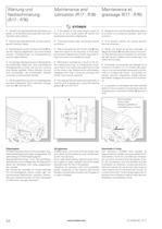
Wartung und Nachschmierung (R17-R76) Maintenance and fabrication (R17-R76) Maintenance et graissage (R17- R76} STOBER Vtersteift 5ich die Drehzahl des Getnebes von sebst. 30 *si die Bremsstfiraube 11) feinter dem Handtad nacftzuziehen. Օ Rutscht das Geinebo dure*», so kann das fol-gende Ursachen haben: Nach lբngerer Laulzerl ist der Laufring 12) bis auf die Fassung abgelaufen und muss erseizt nverden, Ersatzlaulringe mit Etfbauaniertung sind ab Lager lieferbar Kurzzeitige ՙberiastung durct. Bkxfcade der anzutreibenden Masdiine. Sind anschljeliend Ktoplger usdie zu hren, hat sitfi am Laufring...
Open the catalog to page 7
Formeln zur Antriebs- Formulas for slection Formules pour le Auswahl of drive system choix des entrane- ments - G STOBER - P2 = P2 = P2 = P2 = F ■ r ■ n 9550 m- g ■ v 1000 ■n m- g ■ |x- v 1000-n rm g ■ w ■ v 1000 Erforderliche Abtriebsleistung P2 in kW Bei gegebener Ketten-, Band-oder Riemenzugkraft Bei Hubbewegung Bei waagrechter Bewegung Required output power P2 in kW For a given chain or belt pull For lifting motion For horizontal motion Puissance de sortie requise P2 en kW Pour force de traction donn鮩e de la chane, de la bande ou courroieH /A Pour mouvement de levage et de descente Pour mouvement...
Open the catalog to page 8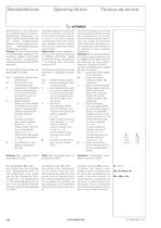
Betriebsfaktoren Operating factors Facteurs de service STOBER Betriebsfaktoren sind Hilfswerte zur Antriebsauswahl, durch die un-gleichfrmige Belastungen, an-dere Laufzeiten als 8 Stunden tag-lich, hhere Umgebungstem-peraturen und der Einsatz unter an-deren Betriebsbedingungen, ber䴹cksichtigt werden. Hinweis: Fr den Einsatz in explo-sionsgefahrdeten Bereichen ent-sprechend 94/9/EG (ATEX100a), bitte zusatzliche Auslegungsvor-schriften gemafS Infoschrift 441677 beachten! Fr die Nachrechnung werden fol-gende Werte ermittelt: M2erf = tatsachlich erforderliches Drehmoment M2 = Drehmoment nach Leistungs鹹bersicht...
Open the catalog to page 9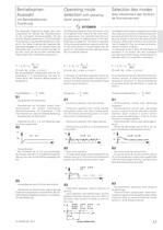
Betriebsarten-Auswahl mit Betriebsfaktoren-Zuordnung Operating mode slection with operating factor assignment Slection des modes avec classement des facteurs de fonctionnement Die folgenden Diagramme zeigen den Leis-tungsverlauf am Abtrieb des Getriebemotors fur die wichtigsten Anwendungsfalle. Die ge-nannten Belastungsfaktoren fB sind Richtwerte fur die Bestimmung des Betriebsfaktors Ki (Sei-te A7). Der Faktor fM gibt bei den folgenden Be-triebsarten dagegen an, um welchen Faktor die Motorleistung Pi aus thermischen Grunden h驴-her sein muss, als die aus dem erforderlichen Drehmoment M2erf errechnete...
Open the catalog to page 10
Betriebsarten-Auswahl mit Betriebsfaktoren-Zuordnung Operating mode slection with operating factor assignment Slection des modes avec classement des facteurs de fonctionnement S4 - Aussetzbetrieb mit Einfluss des Anlaufs - Taktbetrieb mit Bremsmotor, mit einer Mo-tordrehzahl oder polumschaltbarem Motor, gr驴-fere Zusatzschwungmassen S4 - Intermittent operation with influence on starting - Cyclic operation with braking motor, with one motor speed orpole- changing motor, larger ad-ditional flywheel masses S4 - Entranement discontinu avec influence au d뮩marrage Entranement cyclique avec moteur-frein,...
Open the catalog to page 11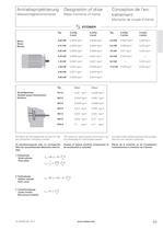
Antriebsprojektierung Dsignation of drive Massentrgheitsmomente Mass moments of inertia Conception de l'en頭tranement Moments de couple d'inertie Motor Motor Moteur Typ 2-polig 2-pole 4-polig 4-pole Typ 2-polig 2-ples 4-polig 4-ples 0,25 kW 0,0002 kgm2 0,0004 kgm2 4,0 kW 0,0045 kgm2 0,009 kgm2 0,37 kW 0,0003 kgm2 0,0004 kgm2 5,5 kW 0,008 kgm2 0,015 kgm2 0,55 kW 0,0003 kgm2 0,0009 kgm2 7,5 kW 0,011 kgm2 0,028 kgm2 0,75 kW 0,0006 kgm2 0,0011 kgm2 9,0 kW 0,026 kgm2 ---- 1,10 kW 0,0007 kgm2 0,0021 kgm2 9,2 kW 0,028 kgm2 1,50 kW 0,0013 kgm2 0,0026 kgm2 11,0 kW 0,026 kgm2 0,035 kgm2 2,20 kW 0,0017...
Open the catalog to page 12All STÖBER catalogs and technical brochures
 Bottom brake resistor
14 Pages
 PS Two-speed Gearbox
26 Pages
 ServoFit Servo Gear Units
539 Pages
 ServoFit® PE
20 Pages
 Synchronous Servo Geared Motors
26 Pages
 SMS PEPlanetary Geared Motors
14 Pages
 STÖBER DIRECT 2011
12 Pages
 ZV Rack and Pinion Drive
2 Pages
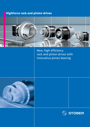 ZTRS Rack and Pinion Drive
6 Pages
 Target Industry Packaging
8 Pages
 Target Industry Machine Tools
12 Pages
 POSIDYN® SDS 5000 Servo Inverter
14 Pages
 PE Planetary Gear Unit
6 Pages
 Energy Efficiency
6 Pages
 SD6 Drive Controller
12 Pages
 MC6 Motion Controller
12 Pages
 Rack and pinion drive ZTRS/ZTR/ZR
180 Pages
 MGS Modular Geared Motors System
325 Pages
 SMS Servo Geared Motors EZ
556 Pages
 MGS AC Geared Motors IE2
285 Pages
 SMS/MGS Gear units
163 Pages
 SMS Servo Geared Motors ED/EK
620 Pages
 ServoCool Planetary gear units
88 Pages

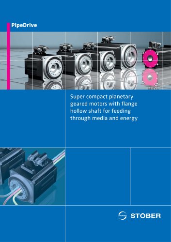


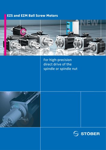

- Planetary gearbox
- Coaxial gearhead
- Precision gearhead
- Servo-motor
- Right angle gearhead
- Compact gearhead
- Solid-shaft gearhead
- Gear train gear reducer
- Gearbox for industrial applications
- Transmission gearhead
- High-performance servo motor
- Shaft gearhead
- AC servo-motor
- Helical gear gearhead
- High-performance gearhead
- Clamp gearbox
- High-precision gearhead
- Electric motor gearhead
- Bevel gearhead
- DC servo-motor