


ServoStop motor adapter integrated brake module

ServoStop motor adapter integrated brake module
The document provides detailed specifications for various models of ServoFit® gear units, including K913_0490MB40, K913_0630MB40, K913_0750MB40, and K913_0950MB40. Key parameters include gear unit type, size, generation number, stages, shaft version, style, transmission ratio, and mounting series. Specific dimensions and tolerances are provided for each model.
Procedures:
Installation guidelines emphasize that vertical motor mounting (EL6) is not permitted if the brake in the motor adapter is part of a redundant braking system. Additional ordering information includes braking torque, terminal box position, and options for manual brake release.
Standards and Norms:
The document references catalog ID 442257 for further motor connection dimensions and emphasizes adherence to specified installation positions and configurations.
Recommendations:
For higher speeds than those listed, consultation is advised. The document also suggests observing maximum dimensions and provides options for manual brake release and electronic monitoring.
Key Data from Tables:
Tables provide detailed measurements for different gear unit types (MB20, MB30, MB40) including dimensions like øb6, øe6, ød2min, ød2max, l5max, and others. Performance data such as maximum input speed, nominal brake torque, and rated torque are also included.
Critical Information:
Attention is drawn to the importance of correct installation and configuration to ensure safety and performance, particularly regarding the use of brakes in redundant systems.
The document provides detailed specifications for various models of ServoFit® gear units, including types MB20, MB30, and MB40. Key parameters include dimensions, input speed, torque, and weight. The gear units are designed for use with motor adapters and brakes, with specific configurations for different applications.
Procedures:
Installation guidelines emphasize that vertical motor mounting is not permitted if the brake is part of a redundant system. The document outlines the necessary steps for proper installation and configuration, including the need for dimension drawings of customer motors.
Standards and Norms:
The document references catalog ID 442257 for additional details on gear unit dimensions and motor connection specifications. It also highlights the importance of adhering to specified operating factors and thermal capacity limits.
Recommendations:
For cycle operation, the document recommends using gear units with shaft design 'G'. It also advises on the selection of braking torque and the positioning of terminal boxes or plug connectors.
Data Summary:
Tables in the document provide comprehensive data on gear unit ratios, maximum input speeds, mass moments of inertia, and permissible torques. These tables are crucial for selecting the appropriate gear unit for specific applications.
Critical Information:
Attention is drawn to the need for careful consideration of operating conditions, such as ambient temperature and load changes, to ensure optimal performance and longevity of the gear units.
The document provides detailed specifications for various planetary gear units and motor adapters with brakes. It includes data on gear unit types, sizes, generation numbers, stages, housing designs, shaft designs, bearing designs, transmission ratios, and mounting series. Specific models such as MB21, MB31, and MB41 are mentioned with their respective dimensions and configurations.
Procedures:
Instructions are provided for ordering and specifying gear units, including the need to indicate mounting sides and positions. The document emphasizes the importance of providing dimension drawings of customer motors and observing maximum dimensions.
Standards and Recommendations:
The document advises against certain installation positions, such as vertical motor mounting when part of a redundant braking system. It also highlights the need to consider operating factors and service conditions as outlined in the ServoFit® catalog ID 442257.
Key Data from Tables:
The tables contain critical data such as maximum input speeds, mass moments of inertia, weights, gear unit backlash, rigidity, noise levels, nominal brake torque, and permissible motor brake torque. These parameters are essential for selecting the appropriate gear unit for specific applications.
Additional Information:
The document includes references to further details in the ServoFit® catalog and provides information on optional features like manual brake release and plug connectors. It also outlines the importance of specifying coil voltage and monitoring systems for wear and air release.
- Gear Unit Types: PHA and PHVA are planetary gear units.
- Sizes and Stages: The document outlines different sizes and stages (1, 2, or 3) for the gear units.
- Design: The gear units feature a flange shaft design.
- Transmission Ratio: Specified as i x 10.
- Mounting Series: Includes motor adapter square with brake for motor shafts without keys.
- Vertical motor mounting (motor down) is prohibited if the brake in the motor adapter is part of a redundant braking system.
- Additional ordering information includes braking torque and terminal box options.
- Symbols: Definitions for gear unit ratio, max input speed, continuous and cycle operation, mass moment of inertia, weight, gear unit backlash, rigidity, noise level, and various torque specifications.
- Performance Data: Tables provide detailed performance metrics for different models, including max input speed, inertia, weight, noise level, and torque values.
- Consider operating factors as specified in the catalog ID 442257.
- Refer to specific pages for additional details and dimension drawings.
Catalog excerpts
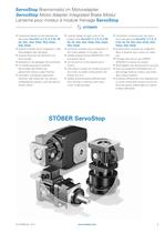
ServoStop Bremsmodul im Motoradapter ServoStop Motor Adapter Integrated Brake Modul Lanterne pour moteur module freinage ServoStop >- STOBER modulares Design fur die Getriebe der Baureihen ServoFit® C, F, K, S, P, PA, PK, PH, PHV, PHA, PHVA, PHQ, PHQA, PHK, PHQK ٠u&erst kompakt durch Integration in den Motoradapter des Getriebes sicheres Bremsen bei NOT-AUS und Stromausfall anbaubar an die gngigen Servomotoren mit Steckkupplung fur einfache Demontage des Motors bei gebremster Achse in jeder Position verhindert zuverlssig ungewolltes Absinken oder Absturzen von schwer-kraftbelasteten Achsen, auch...
Open the catalog to page 3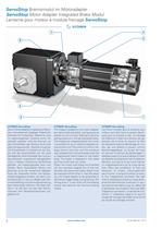
ServoStop Bremsmodul im Motoradapter ServoStop Motor Adapter Integrated Brake Modul Lanterne pour moteur module freinage ServoStop STOBER 3 STOBER ServoStop Die im Motoradapter eingebauten Brem-sen sind elektrisch betatigte Federkraft-bremsen fur Trockenlauf. Gebremst wird im spannungslosen Zustand durch Fe-derkraft; geluftet wird die Bremse vor dem Einschalten des Motors durch eine elektromagnetische Gleichstromspule. Die Einschaltzeit t2 (Luftzeit) ist die Zeit, bis sich die Ankerscheibe von der axial beweglichen Bremsscheibe lst und am Spulenkഴrper magnetisch festgehalten wird. In diesem Zustand...
Open the catalog to page 4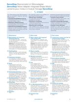
ServoStop Bremsmodul im Motoradapter ServoStop Motor Adapter Integrated Brake Modul Lanterne pour moteur module freinage ServoStop Zur Uberwachung des Bremssystems gibt es prinzipiell folgende optionale Mglichkeiten: ക manuelle Verschleiftberwachung Luftspaltuberprufung mit Fuhlerlehre (standardmaftig mglich) 鴕 elektrische Lftberwachung standardmaftig im Klemmenkasten der Motoradapterbremse integriert 鹕 elektrische Verschleiftberwachung optional im Klemmenkasten mglich, Funktion jedoch auch indirekt durch die Luftuberwachung erfullt - 鴙>- STOBER - The following options are available for monitoring...
Open the catalog to page 5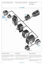
Allgemeine Anmerkungen: General Notes: Remarques gnrales: 驕 Allgemeine Hinweise zu Wellenbelastun-gen, Antriebsprojektierung und Wellenausfh-rungen siehe A-Block, Katalog ServoFit® Servo-getriebe (ID 442257). Getriebe mit Bremsmodul im Motoradapter sind nicht f镹r den Einsatz in explosionsge-schtzten Bereichen (ATEX) geeignet. For g镩nral information on shaft loads, drive slection and shaft design, please see ServoFit® Servo Gear Units catalog, block A (ID 442257). 驕 Gear units with a motor adapter integrated brake module are not suitable for operation in explosion-proof areas (ATEX). Instructions...
Open the catalog to page 6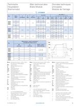
Technische Hauptdaten: Bremsmodul Main technical data: Brake Module Donnes techniques principales: Module de freinage Typ MlHN [Nm] Jl [10-4kgm2] G [kg] A>b 2) [arcmin] UDC 24 V UDC 104 V 1) UAC220 - 277 V, 50 // 60 Hz t1DC [ms] t2 [ms] P20 [W] t1DC [ms] t1AC [ms] t2 [ms] P20 [W] 4) P20 [W] 5) MB20 MB21 MB22 8 7,2 7,4 32 100 35 30 80 350 25 101 26 12 80 46 60 290 30 16D - - 50 260 35 24D - - 42 230 44 MB30 MB31 MB32 16 16,5 12,8 26 150 45 37 100 500 35 125 32 24 150 60 90 450 45 32 125 70 85 410 50 45 107 95 74 336 75 MB40 MB41 MB42 50 65,9 24,5 19 200 110 55 150 600 100 148 38 72 150 120 120...
Open the catalog to page 7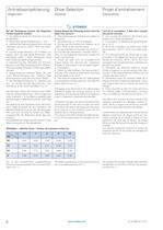
Antriebsprojektierung Drive Slection Projet d'entranement Allgemein General G鮩nralits STOBER Bei der Auslegung m驹ssen die folgenden Punkte beachtet werden: die Haltemomente von Bremsen sind tole-ranzbehaftet Օ ServoStop hat bei Auslieferung +/- 15% wahrend der Gebrauchsdauer kann sich dies verandern, bis hin zu +40% / -20% vom Nenn-moment Օ ist eine zweite Bremse, z. B. im Motor, an-gebaut, dann hat auch diese Toleranzen - bli-cherweise +40% / -20%, Genaueres muss beim Motorhersteller erfragt werden 镙berprfung des Getriebes auf Not-Aus-Moment unter Bercksichtigung der +Toleranz (Momente beider...
Open the catalog to page 8
Antriebsprojektierung Drive Slection Projet d'entranement Formeln Formula Formules STOBER Belastungsgrad der Bremse durch das Lastmo-ment: Utilization factor for the brake due to the load torque: Facteur de charge du frein par le couple de char鮭ge admissible : _ MLJ1 ) r MB _ MLJ1 ) BG = 100 BG = 100 BG =100 Mb MB MB Verhaltnis der Massentragheitsmomente der Last zum Antrieb: Ratio of the mass moments of inertia of the load and the drive: Rapport entre les moments d'inertie de la charge et l'entraͮnement : i2 j1 i2 Օ J1 i2 J1 ՙberprfung auf sicheres Halten: Check for safe holding: Vrification...
Open the catalog to page 9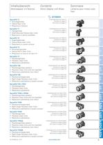
ServoFit® C Stirnradgetriebe Օ Helical Gear Units Rducteurs coaxiaux ServoFit® F Flachgetriebe 镕 Shaft-Mounted Helical Gear Units Rթducteurs arbres parallles ServoFit® K ਕ Kegelradgetriebe Helical Bevel Gear Units Օ Rducteurs couple conique ServoFit® S 頕 Schneckengetriebe Helical Worm Gear Units Օ Rducteurs roue et vis sans fin ServoFit® P 頕 Planetengetriebe Planetary Gear Units Օ Rducteurs plantaires ServoFit® PA 驕 Planetengetriebe spielarm Planetary Gear Units with low backlash Օ Rducteurs plantaires 驠 jeu rduit ServoFit® PK Planetenwinkelgetriebe 镕 Right-Angle Planetary Gear Units...
Open the catalog to page 11
Inhaltsbersicht C Contents C Sommaire C Typenbezeichnung - Ausfhrungsformen C2 Type d鹩signation -Available combinations C2 Dsignation des types - Auswahlliste: Selection data: Types de constructions C2 ServoFit® Stirnradgetriebe C C3 ServoFit® C Helical Gear Units C3 Liste des alternatives: Mafbilder: Dimensioned drawings: R髩ducteurs coaxiaux ServoFit® CC3 ServoFit® Stirnradgetriebe C C25 ServoFit® C Helical Gear Units C25 Croquis cots: Rducteurs coaxiaux ServoFit® C C25 ID 441904.04 - 0711 www.stober.com C1
Open the catalog to page 12
Auswahlliste: Selecbn data: Liste des alternatives: ServoFit® ServoFit® C Helil Gear Rducteurs coaxiaux Stimradgetriebe C UnitS Motor Adapter with Brake ServoFit® C lanterne Motoradapter mit Bremse pour moteur avec frein - fi STOBER - 1)441904.04-0711 www.stobercom C3
Open the catalog to page 14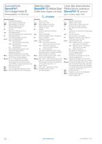
Auswahlliste: ServoFit® Stirnradgetriebe C Motoradapter mit Bremse Slection data: ServoFit® C Helical Gear Units MotorAdapterwith Brake Liste des alternatives: Rducteurs coaxiaux ServoFit® C lanterne pour moteur avec frein STOBER Bezeichnungen: i - Getriebe驹bersetzung iexakt - math. genaue bersetzung MB - Motoradapter mit Bremse Ji - Massentragheitsmoment (auf Eintrieb bezogen] G -Gewicht (Bauart N, ٔlmenge fr EL1) Ap2 - Getriebedrehspiel (ohne Drehspiel Bremse, siehe Seite 5] C2 - Getriebesteifigkeit (auf Abtrieb bezogen bei M2N] niMAX - max. Eintriebsdrehzahl DBH - Dauerbetrieb - Motoranschluss...
Open the catalog to page 15All STÖBER catalogs and technical brochures
 Bottom brake resistor
14 Pages
 PS Two-speed Gearbox
26 Pages
 ServoFit Servo Gear Units
539 Pages
 ServoFit® PE
20 Pages
 Synchronous Servo Geared Motors
26 Pages
 SMS PEPlanetary Geared Motors
14 Pages
 STÖBER DIRECT 2011
12 Pages
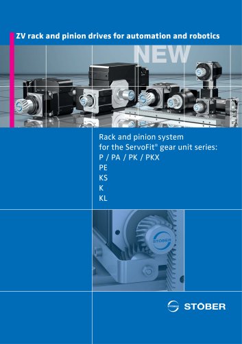 ZV Rack and Pinion Drive
2 Pages
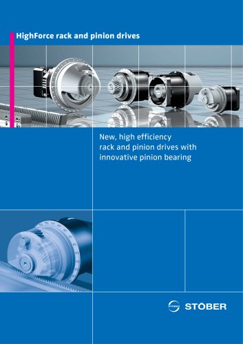 ZTRS Rack and Pinion Drive
6 Pages
 Target Industry Packaging
8 Pages
 Target Industry Machine Tools
12 Pages
 POSIDYN® SDS 5000 Servo Inverter
14 Pages
 PE Planetary Gear Unit
6 Pages
 Energy Efficiency
6 Pages
 SD6 Drive Controller
12 Pages
 MC6 Motion Controller
12 Pages
 Rack and pinion drive ZTRS/ZTR/ZR
180 Pages
 MGS Modular Geared Motors System
325 Pages
 SMS Servo Geared Motors EZ
556 Pages
 MGS AC Geared Motors IE2
285 Pages
 Variable speed drives
243 Pages
 SMS/MGS Gear units
163 Pages
 SMS Servo Geared Motors ED/EK
620 Pages
 ServoCool Planetary gear units
88 Pages



- Planetary gearbox
- Coaxial gearhead
- Precision gearhead
- Servo-motor
- Right angle gearhead
- Compact gearhead
- Solid-shaft gearhead
- Gear train gear reducer
- Gearbox for industrial applications
- Transmission gearhead
- High-performance servo motor
- Shaft gearhead
- AC servo-motor
- Helical gear gearhead
- High-performance gearhead
- Clamp gearbox
- High-precision gearhead
- Electric motor gearhead
- Bevel gearhead
- Ultra-compact servomotor