Bottom brake resistor
1 /14Pages

Bottom brake resistor
1 /14Pages
Catalog excerpts

Bottom brake resistor Commissioning Instructions Technical data Installation
Open the catalog to page 1
Table of contents Commissioning Instructions Bottom brake resistor Table of contents 1 Notes on Safety. . . . . . . . . . . . . . . . . . . . . . . . . . 1.1 Component part of the product . . . . . . . . . . . . . . . . . . . . . . . . 1.2 Operation in accordance with its intended use . . . . . . . . . . . . 1.5 Commissioning, operation and service . . . . . . . . . . . . . . . . . . 1.7 Presentation of notes on safety. . . . . . . . . . . . . . . . . . . . . . . . WE KEEP THINGS MOVING
Open the catalog to page 2
Notes on Safety Commissioning Instructions Bottom brake resistor 0 STOBER _ The devices may cause risks. For these reasons, comply with the following: • The safety notes listed in the following sections and points • The technical rules and regulations. In addition, always read the appropriate documentation. STOBER ANTRIEBSTECHNIK GmbH + Co. KG accepts no liability for damages caused by non-adherence to the instructions or applicable regulations. Subject to technical changes to improve the devices without prior notice. This documentation is purely a product description. It does not represent promised...
Open the catalog to page 3
Tab. 1-1: examples of occupational qualifications In addition, the valid regulations, the legal requirements, the reference books, this technical documentation and, in particular, the safety information contained therein must be carefully • read • understood and • complied with 1.4 Installation and connection Installation and connection work are only permitted after the device has been isolated from the power! The accessory installation instructions allow the following actions during the installation of accessories: • The housing in the upper slot can be opened • The housing in the bottom slot...
Open the catalog to page 4
Notes on Safety Commissioning Instructions Bottom brake resistor Commissioning, operation and service Remove additional coverings before commissioning so that the device cannot overheat. During installation, provide the free spaces specified in the projecting manuals to prevent the inverter from overheating. The housing of the drive controller must be closed before you turn on the supply voltage. When the supply voltage is on, dangerous voltages can be present on the connection terminals and the cables and motor terminals connected to them. Remember that the device is not necessarily de-energized...
Open the catalog to page 5
Notes on Safety Commissioning Instructions Bottom brake resistor _ ^ STOBER Notice means that property damage may occur ► if the stated precautionary measures are not taken. Caution with warning triangle means that minor injury may occur ► if the stated precautionary measures are not taken. A WARNING! Warning means that there may be a serious danger of death ► if the stated precautionary measures are not taken. Danger means that serious danger of death exists ► if the stated precautionary measures are not taken. O Information indicates important information about the product or a highlighted...
Open the catalog to page 6
Technical data Commissioning Instructions Bottom brake resistor 2 Technical data See installation on inverter (chapter 4)!
Open the catalog to page 7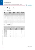
Assignment Commissioning Instructions Bottom brake resistor _ ^ STOBER
Open the catalog to page 8
Assignment Commissioning Instructions Bottom brake resistor 0 STOBER _
Open the catalog to page 9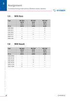
Assignment Commissioning Instructions Bottom brake resistor _ ^ STOBER
Open the catalog to page 10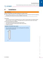
Installation Commissioning Instructions Bottom brake resistor Installation WARNING! Danger of injury/death and property damage due to electric shock! Before installing accessories, turn off all voltage supplies! Then wait 5 minutes for the DC link capacitors to discharge. Never begin with accessory installation until after this! Prerequisites: • You have bored the holes for threaded bolts (as per chapter 2 Technical data) in the switching cabinet where the inverter is to be installed. The threaded bolts are included with the bottom brake resistor. You will need the following for installation:...
Open the catalog to page 11
Installation Commissioning Instructions Bottom brake resistor Place the inverter on the guide rails: WE KEEP THINGS MOVING Press the inverter downwards on the guide rails: Secure the inverter to the threaded bolts with the screws and washers: You have now installed the bottom brake resistor.
Open the catalog to page 12
Address registers Always up to date on the internet: www.stober.com ^ contact • Technical Offices (TB) for advice and marketing in Germany • Global presence for advice and marketing in about 25 countries • Service Network Germany • Service Network International • STOBER Subsidiaries: STOBER ANTRIEBSTECHNIK GmbH STOBER DRIVES INC. 1781 Downing Drive Maysville, KY 41056 Fon +1 606 7595090 Fax +1 606 7595045 eMail: [email protected] www.stober.com STOBER S.a.r.l. 131, Chemin du Bac a Traille Les Portes du Rhone 69300 Caluire et Cuire Fon +33478989180 Fax +33 4 78985901 eMail: [email protected] www.stober.fr...
Open the catalog to page 13
STOBER ANTRIEBSTECHNIK GmbH + Co. KG Kieselbronner Str. 12 75177 PFORZHEIM GERMANY Tel. +49 (0)7231 582-0 Fax. +49 (7231) 582-1000 E-Mail: [email protected] Technische Anderungen vorbehalten Errors and changes excepted ID 441806.03 04/2012
Open the catalog to page 14All STÖBER catalogs and technical brochures
 PS Two-speed Gearbox
26 Pages
 ServoFit Servo Gear Units
539 Pages
 ServoFit® PE
20 Pages
 Synchronous Servo Geared Motors
26 Pages
 SMS PEPlanetary Geared Motors
14 Pages
 STÖBER DIRECT 2011
12 Pages
 ZV Rack and Pinion Drive
2 Pages
 ZTRS Rack and Pinion Drive
6 Pages
 Target Industry Packaging
8 Pages
 Target Industry Machine Tools
12 Pages
 POSIDYN® SDS 5000 Servo Inverter
14 Pages
 PE Planetary Gear Unit
6 Pages
 Energy Efficiency
6 Pages
 SD6 Drive Controller
12 Pages
 MC6 Motion Controller
12 Pages
 Rack and pinion drive ZTRS/ZTR/ZR
180 Pages
 MGS Modular Geared Motors System
325 Pages
 SMS Servo Geared Motors EZ
556 Pages
 MGS AC Geared Motors IE2
285 Pages
 Variable speed drives
243 Pages
 SMS/MGS Gear units
163 Pages
 SMS Servo Geared Motors ED/EK
620 Pages
 ServoCool Planetary gear units
88 Pages


- Planetary gearbox
- Coaxial gearhead
- Precision gearhead
- Right angle gearhead
- Servo-motor
- Compact gearhead
- Solid-shaft gearhead
- Gear train gear reducer
- Gearbox for industrial applications
- Transmission gearhead
- Shaft gearhead
- AC servo-motor
- High-performance servo motor
- Helical gear gearhead
- High-performance gearhead
- Clamp gearbox
- High-precision gearhead
- Bevel gearhead
- Electric motor gearhead
- DC servo-motor