- Catalogs
- STMicroelectronics
- VL53L0X
VL53L0X
1 /40Pages

VL53L0X
1 /40Pages
Catalog excerpts

VL53L0XWorld’s smallest Time-of-Flight ranging and gesture detection sensor Datasheet - production data Features • Fully integrated miniature module - 940 nm laser VCSEL - VCSEL driver - Ranging sensor with advanced embedded micro controller - 4.4 x 2.4 x 1.0 mm • Fast, accurate distance ranging - Measures absolute range up to 2 m - Reported range is independent of the target reflectance - Advanced embedded optical cross-talk compensation to simplify cover glass selection • Eye safe - Class 1 laser device compliant with latest standard IEC 60825-1:2014 - 3rd edition • Easy integration - Single reflowable component - No additional optics - Single power supply - I2C interface for device control and data transfer - Xshutdown (reset) and interrupt GPIO - Programmable I2C address Applications • User detection for personal computers/ laptops/tablets and loT (energy saving) • Robotics (obstacle detection) • White goods (hand detection in automatic faucets, soap dispensers etc.) • 1D gesture recognition. • Laser assisted autofocus. Enhances and speeds up camera autofocus system performance, especially in difficult scenes (low light levels, low contrast) or fast moving video mode. Description The VL53L0X is a new generation Time-of-Flight (ToF) laser-ranging module housed in the smallest package on the market today, providing accurate distance measurement whatever the target reflectances unlike conventional technologies. It can measure absolute distances up to 2m, setting a new benchmark in ranging performance levels, opening the door to various new applications. The VL53L0X integrates a leading-edge SPAD array (Single Photon Avalanche Diodes) and embeds ST’s second generation FlightSense™ patented technology. The VL53L0X’s 940 nm VCSEL emitter (Vertical Cavity Surface-Emitting Laser), is totally invisible to the human eye, coupled with internal physical infrared filters, it enables longer ranging distances, higher immunity to ambient light, and better robustness to cover glass optical crosstalk. This is information on a product in full production. www.st.com
Open the catalog to page 1
System block diagram . . . . . . . . . . . . . . . . . . . . . . . . . . . . . . . . . . . . . . . . 6 System functional description . . . . . . . . . . . . . . . . . . . . . . . . . . . . . . . . . . . 9 Firmware state machine description . . . . . . . . . . . . . . . . . . . . . . . . . . . . . 10 Customer manufacturing calibration flow . . . . . . . . . . . . . . . . . . . . . . . . . .11 2.3.1 SPAD and temperature calibration . . . . . . . . . . . . . . . . . . . . . . . . . . . . 12 Ranging offset calibration . . . . . . . . . . . . . . . . . . . . . . . . . . . . . . . . . . . 12 Ranging...
Open the catalog to page 2
Range profile examples . . . . . . . . . . . . . . . . . . . . . . . . . . . . . . . . . . . . . 28 Ranging offset error . . . . . . . . . . . . . . . . . . . . . . . . . . . . . . . . . . . . . . . . 28 Laser safety considerations . . . . . . . . . . . . . . . . . . . . . . . . . . . . . . . . . . 32 Tape outline drawings . . . . . . . . . . . . . . . . . . . . . . . . . . . . . . . . . . . . . . 34 Pb-free solder reflow process . . . . . . . . . . . . . . . . . . . . . . . . . . . . . . . . . . 34 Handling and storage precautions . . . . . . . . . . . . . . . . . . . . . . . . . . . . . . 36...
Open the catalog to page 3
List of tables Table 1. Table 2. Table 3. Table 4. Table 5. Table 6. Table 7. Table 8. Table 9. Table 10. Table 11. Table 12. Table 13. Table 14. Table 15. Table 16. Table 17. Table 18. Table 19. Technical specification . . . . . . . . . . . . . . . . . . . . . . . . . . . . . . . . . . . . . . . . . . . . . . . . . . . . . 6 VL53L0X pin description . . . . . . . . . . . . . . . . . . . . . . . . . . . . . . . . . . . . . . . . . . . . . . . . . . . . 7 I2C interface - timing characteristics . . . . . . . . . . . . . . . . . . . . . . . . . . . . . . . . . . . . . . . . . 20 Reference registers...
Open the catalog to page 4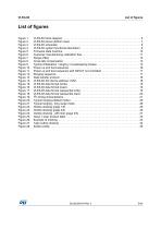
List of figures Figure 1. Figure 2. Figure 3. Figure 4. Figure 5. Figure 6. Figure 7. Figure 8. Figure 9. Figure 10. Figure 11. Figure 12. Figure 13. Figure 14. Figure 15. Figure 16. Figure 17. Figure 18. Figure 19. Figure 20. Figure 21. Figure 22. Figure 23. Figure 24. Figure 25. Figure 26. Figure 27. Figure 28. VL53L0X block diagram . . . . . . . . . . . . . . . . . . . . . . . . . . . . . . . . . . . . . . . . . . . . . . . . . . . . 6 VL53L0X pinout (bottom view) . . . . . . . . . . . . . . . . . . . . . . . . . . . . . . . . . . . . . . . . . . . . . . . 7 VL53L0X schematic . . . . . . ....
Open the catalog to page 5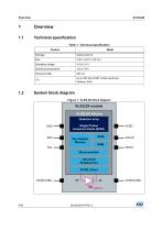
Table 1. Technical specification Figure 1. VL53L0X block diagram
Open the catalog to page 6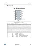
Device pinout Figure 2 shows the pinout of the VL53L0X (see also Figure 22).
Open the catalog to page 7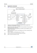
Application schematic Figure 3 shows the application schematic of the VL53L0X. Figure 3. VL53L0X schematic Note: Note: Note: Note: Note: Capacitors on external supply AVDD should be placed as close as possible to the AVDDVCSEL and AVSSVCSEL module pins. External pull-up resistors values can be found in I2C-bus specification. Pull-up are typically fitted only once per bus, near the host. Recommended values for pull-up resistors for an AVDD of 2.8V and 400KHz I2C clock would be 1.5k to 2k Ohms. XSHUT pin must always be driven to avoid leakage current. Pull-up is needed if the host state is not...
Open the catalog to page 8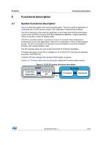
Functional description Functional description System functional description Figure 4 shows the system level functional description. The host customer application is controlling the VL53L0X device using an API (Application Programming Interface). The API is exposing to the customer application a set of high level functions that allows control of the VL53L0X Firmware (FW) like initialization/calibration, ranging Start/Stop, choice of accuracy, choice of ranging mode. The API is a turnkey solution, it consists of a set of C functions which enables fast development of end user applications, without...
Open the catalog to page 9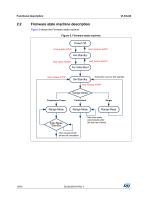
Functional description Firmware state machine description Figure 5 shows the Firmware state machine. Figure 5. Firmware state machine
Open the catalog to page 10All STMicroelectronics catalogs and technical brochures
 STGW30NC60KD
14 Pages
 STGB14NC60K STGD14NC60K
16 Pages
 HD1750FX
8 Pages
 TDA75610SLV
42 Pages
 TDA7391
13 Pages
 TDA7376B
15 Pages
 TDA7375V
15 Pages
 TDA2005
25 Pages
 L4989D, L4989MD
19 Pages
 L4938ED L4938EPD
20 Pages
 L4949ED-E L4949EP-E
19 Pages
 L4925
L492514 Pages
 FDA903U
80 Pages
 FDA803U
76 Pages
 FDA903D
82 Pages
 FDA803D
78 Pages
 BALF-SPI2-02D3
13 Pages
 LIS2DTW12
65 Pages
 LPS22HH
59 Pages
 Standard products offer overview
13 Pages
 M40SZ100W
20 Pages
 A1C15S12M3
17 Pages
 TSX923
32 Pages
 TS1851
24 Pages
 LMV321
17 Pages
 Serial real-time clock (RTC) ICs
16 Pages
 TDA2003LG
8 Pages
 HCF4541 Programmable Timer
10 Pages
 STA8058 GPS multi-chip module
14 Pages
 TDA7410ND Signal Processor
34 Pages
 TDA7410ND Signal Processor
34 Pages
 TSA1204 DUAL CHANNEL
31 Pages


Archived catalogs
 NEATSwitch
6 Pages
 Power MOSFETs for metering
2 Pages


- Single-pole switch
- Acceleration sensor
- Pressure probe
- Technology switch
- Signal amplifying integrated circuit
- Multipole switch
- Piezoelectric accelerometer
- Transceiver module
- Electronic filter
- Electromechanical switch
- Membrane pressure sensor
- Analog pressure sensor
- Rotary electric switch
- Triaxial acceleration sensor
- Power amplifying integrated circuit
- Distance sensor
- STMicroelectronics transistor
- Low-pass electronic filter
- Absolute pressure sensor