- Catalogs
- STMicroelectronics
- STM32F101RE Access line, advanced ARM-based 32-bit MCU with Flash memory, six 16-bit timers, ADC and seven communication interfaces
STM32F101RE Access line, advanced ARM-based 32-bit MCU with Flash memory, six 16-bit timers, ADC and seven communication interfaces
1 /112Pages

STM32F101RE Access line, advanced ARM-based 32-bit MCU with Flash memory, six 16-bit timers, ADC and seven communication interfaces
1 /112Pages
Catalog excerpts

April 2011 Doc ID 14610 Rev 8 1/112 1 STM32F101xC STM32F101xD STM32F101xE High-density access line, ARM-based 32-bit MCU with 256 to 512 KB Flash, 9 timers, 1 ADC and 10 communication interfaces Features ¡ Core: ARM 32-bit Cortex™-M3 CPU – 36 MHz maximum frequency, 1.25 DMIPS/MHz (Dhrystone 2.1) performance – Single-cycle multiplication and hardware division ¡ Memories – 256 to 512 Kbytes of Flash memory – up to 48 Kbytes of SRAM – Flexible static memory controller with 4 Chip Select. Supports Compact Flash, SRAM, PSRAM, NOR and NAND memories – LCD parallel interface, 8080/6800 modes ¡ Clock, reset and supply management – 2.0 to 3.6 V application supply and I/Os – POR, PDR, and programmable voltage detector (PVD) – 4-to-16 MHz crystal oscillator – Internal 8 MHz factory-trimmed RC – Internal 40 kHz RC with calibration capability – 32 kHz oscillator for RTC with calibration ¡ Low power – Sleep, Stop and Standby modes – VBAT supply for RTC and backup registers ¡ 1 x 12-bit, 1 ìs A/D converters (up to 16 channels) – Conversion range: 0 to 3.6 V – Temperature sensor ¡ 2 × 12-bit D/A converters ¡ DMA – 12-channel DMA controller – Peripherals supported: timers, ADC, DAC, SPIs, I2Cs and USARTs ¡ Up to 112 fast I/O ports – 51/80/112 I/Os, all mappable on 16 external interrupt vectors and almost all 5 V-tolerant ¡ Debug mode – Serial wire debug (SWD) & JTAG interfaces – Cortex-M3 Embedded Trace Macrocell™ ¡ Up to 9 timers – Up to four 16-bit timers, each with up to 4 IC/OC/PWM or pulse counters – 2 × watchdog timers (Independent and Window) – SysTick timer: a 24-bit downcounter – 2 × 16-bit basic timers to drive the DAC ¡ Up to 10 communication interfaces – Up to 2 x I2C interfaces (SMBus/PMBus) – Up to 5 USARTs (ISO 7816 interface, LIN, IrDA capability, modem control) – Up to 3 SPIs (18 Mbit/s) ¡ CRC calculation unit, 96-bit unique ID ¡ ECOPACK® packages Table 1. Device summary Reference Part number STM32F101xC STM32F101RC STM32F101VC STM32F101ZC STM32F101xD STM32F101RD STM32F101VD STM32F101ZD STM32F101xE STM32F101RE STM32F101ZE STM32F101VE LQFP144 20 × 20 mm LQFP64 10 × 10 mm LQFP100 14 × 14 mm www.st.com
Open the catalog to page 1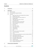
Contents STM32F101xC, STM32F101xD, STM32F101xE 2/112 Doc ID 14610 Rev 8 Contents 1 Introduction . . . . . . . . . . . . . . . . . . . . . . . . . . . . . . . . . . . . . . . . . . . . . . . . 9 2 Description . . . . . . . . . . . . . . . . . . . . . . . . . . . . . . . . . . . . . . . . . . . . . . . . 10 2.1 Device overview . . . . . . . . . . . . . . . . . . . . . . . . . . . . . . . . . . . . . . . . . . . . 11 2.2 Full compatibility throughout the family . . . . . . . . . . . . . . . . . . . . . . . . . . 14 2.3 Overview . . . . . . . . . . . . . . . . . . . . . . . . . . . . . . . . . ....
Open the catalog to page 2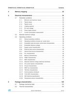
STM32F101xC, STM32F101xD, STM32F101xE Contents Doc ID 14610 Rev 8 3/112 4 Memory mapping . . . . . . . . . . . . . . . . . . . . . . . . . . . . . . . . . . . . . . . . . . 33 5 Electrical characteristics . . . . . . . . . . . . . . . . . . . . . . . . . . . . . . . . . . . . 34 5.1 Parameter conditions . . . . . . . . . . . . . . . . . . . . . . . . . . . . . . . . . . . . . . . . 34 5.1.1 Minimum and maximum values . . . . . . . . . . . . . . . . . . . . . . . . . . . . . . . 34 5.1.2 Typical values . . . . . . . . . . . . . . . . . . . . . . . . . . . . . . . . . . . . . . . . . . . . . 34...
Open the catalog to page 3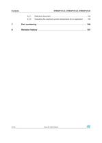
Contents STM32F101xC, STM32F101xD, STM32F101xE 4/112 Doc ID 14610 Rev 8 6.2.1 Reference document . . . . . . . . . . . . . . . . . . . . . . . . . . . . . . . . . . . . . . 104 6.2.2 Evaluating the maximum junction temperature for an application . . . . 105 7 Part numbering . . . . . . . . . . . . . . . . . . . . . . . . . . . . . . . . . . . . . . . . . . . 106 8 Revision history . . . . . . . . . . . . . . . . . . . . . . . . . . . . . . . . . . . . . . . . . . 107
Open the catalog to page 4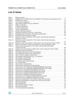
STM32F101xC, STM32F101xD, STM32F101xE List of tables Doc ID 14610 Rev 8 5/112 List of tables Table 1. Device summary . . . . . . . . . . . . . . . . . . . . . . . . . . . . . . . . . . . . . . . . . . . . . . . . . . . . . . . . . . 1 Table 2. STM32F101xC, STM32F101xD and STM32F101xE features and peripheral counts . . . . 11 Table 3. STM32F101xx family . . . . . . . . . . . . . . . . . . . . . . . . . . . . . . . . . . . . . . . . . . . . . . . . . . . . . 14 Table 4. Timer feature comparison. . . . . . . . . . . . . . . . . . . . . . . . . . . . . . . . . . . . . . . . . . . . . . . . . . 19...
Open the catalog to page 5
List of tables STM32F101xC, STM32F101xD, STM32F101xE 6/112 Doc ID 14610 Rev 8 Table 46. I/O static characteristics . . . . . . . . . . . . . . . . . . . . . . . . . . . . . . . . . . . . . . . . . . . . . . . . . . . 80 Table 47. Output voltage characteristics . . . . . . . . . . . . . . . . . . . . . . . . . . . . . . . . . . . . . . . . . . . . . . 83 Table 48. I/O AC characteristics . . . . . . . . . . . . . . . . . . . . . . . . . . . . . . . . . . . . . . . . . . . . . . . . . . . . . 84 Table 49. NRST pin characteristics . . . . . . . . . . . . . . . . . . . . . . . . . . . . . . . . ....
Open the catalog to page 6
STM32F101xC, STM32F101xD, STM32F101xE List of figures Doc ID 14610 Rev 8 7/112 List of figures Figure 1. STM32F101xC, STM32F101xD and STM32F101xE access line block diagram . . . . . . . . 12 Figure 2. Clock tree . . . . . . . . . . . . . . . . . . . . . . . . . . . . . . . . . . . . . . . . . . . . . . . . . . . . . . . . . . . . . . 13 Figure 3. STM32F101xC, STM32F101xD and STM32F101xE access line LQFP144 pinout . . . . . . 23 Figure 4. STM32F101xC, STM32F101xD and STM32F101xE LQFP100 pinout . . . . . . . . . . . . . . . 24 Figure 5. STM32F101xC, STM32F101xD and STM32F101xE LQFP64 pinout . ....
Open the catalog to page 7
List of figures STM32F101xC, STM32F101xD, STM32F101xE 8/112 Doc ID 14610 Rev 8 Figure 41. 5 V tolerant I/O input characteristics - CMOS port . . . . . . . . . . . . . . . . . . . . . . . . . . . . . . . 82 Figure 42. 5 V tolerant I/O input characteristics - TTL port . . . . . . . . . . . . . . . . . . . . . . . . . . . . . . . . . 82 Figure 43. I/O AC characteristics definition . . . . . . . . . . . . . . . . . . . . . . . . . . . . . . . . . . . . . . . . . . . . . 85 Figure 44. Recommended NRST pin protection . . . . . . . . . . . . . . . . . . . . . . . . . . . . . . . . . . . . . . . . ....
Open the catalog to page 8All STMicroelectronics catalogs and technical brochures
 STGW30NC60KD
14 Pages
 STGB14NC60K STGD14NC60K
16 Pages
 HD1750FX
8 Pages
 TDA75610SLV
42 Pages
 TDA7391
13 Pages
 TDA7376B
15 Pages
 TDA7375V
15 Pages
 TDA2005
25 Pages
 L4989D, L4989MD
19 Pages
 L4938ED L4938EPD
20 Pages
 L4949ED-E L4949EP-E
19 Pages
 L4925
L492514 Pages
 FDA903U
80 Pages
 FDA803U
76 Pages
 FDA903D
82 Pages
 FDA803D
78 Pages
 BALF-SPI2-02D3
13 Pages
 LIS2DTW12
65 Pages
 VL53L0X
40 Pages
 LPS22HH
59 Pages
 Standard products offer overview
13 Pages
 M40SZ100W
20 Pages
 A1C15S12M3
17 Pages
 TSX923
32 Pages
 TS1851
24 Pages
 LMV321
17 Pages
 Serial real-time clock (RTC) ICs
16 Pages
 TDA2003LG
8 Pages
 HCF4541 Programmable Timer
10 Pages
 STA8058 GPS multi-chip module
14 Pages
 TDA7410ND Signal Processor
34 Pages
 TDA7410ND Signal Processor
34 Pages
 TSA1204 DUAL CHANNEL
31 Pages


Archived catalogs
 NEATSwitch
6 Pages
 Power MOSFETs for metering
2 Pages


- Bourn And Koch single-pole switch
- Bourn And Koch accelerometer
- Bourn And Koch pressure sensor
- Technology switch
- Bourn And Koch signal amplifier
- Multipole switch
- Piezoelectric accelerometer
- Bourn And Koch transceiver
- Bourn And Koch electronic filter
- Electromechanical switch
- Bourn And Koch membrane pressure sensor
- Bourn And Koch analog pressure sensor
- Rotary electric switch
- Triaxial acceleration sensor
- Bourn And Koch power amplifier
- Distance sensor
- Diode
- Bourn And Koch transistor
- Low-pass electronic filter
- Absolute pressure sensor