- Catalogs
- STMicroelectronics
- M41ST85WSerial real-time clock (RTC) supervisor
M41ST85WSerial real-time clock (RTC) supervisor
1 /43Pages

M41ST85WSerial real-time clock (RTC) supervisor
1 /43Pages
Catalog excerpts

M41ST85W 3.0/3.3 V I2C combination serial RTC, NVRAM supervisor and microprocessor supervisor Features SNAPHAT battery & crystal Automatic battery switchover and WRITE protect for: – Internal serial RTC and – External low power SRAM (LPSRAM) Ultralow battery supply current of 500 nA (max) RoHS compliant – Lead-free second level interconnect 44 bytes of general purpose NVRAM Counters for: – Seconds, minutes, hours, day, date, month, and year – Century – Tenths/hundredths of seconds – Clock calibration register allows compensation for crystal variations over temperature Power-on reset/low voltage detect – Open drain reset output – Reset voltage, VPFD = 2.60 V (nom) – Two reset input pins – Watchdog can be steered to reset output NVRAM supervisor features Battery monitor (battery low flag) Programmable alarm with repeat modes – Functions in battery back-up mode Non-volatizes external LPSRAM – Automatically switches to back-up battery and deselects (write-protects) external LPSRAM via chip-enable gate – Power-fail deselect (write protect) voltage, VPFD = 2.60 V (nom) – Switchover, VSO = 2.50 V (nom) 2.5 to 5.5 V oscillator operating voltage Microprocessor supervisor features ■ Other features Programmable watchdog – 62.5 ms to 128 s time-out period Early power-fail warning circuit (PFI/PFO) with 1.25 V precision reference Programmable squarewave generator (1 Hz to 32 KHz) Package options: – 28-lead SNAPHAT® IC (SOH28) SNAPHAT battery/crystal top to be ordered separately – 28-lead embedded crystal SOIC (SOX28)
Open the catalog to page 1
Start data transfer . . . . . . . . . . . . . . . . . . . . . . . . . . . . . . . . . . . . . . . . . 13 Stop data transfer . . . . . . . . . . . . . . . . . . . . . . . . . . . . . . . . . . . . . . . . . 13 Data retention mode . . . . . . . . . . . . . . . . . . . . . . . . . . . . . . . . . . . . . . . . . 17 Setting alarm clock registers . . . . . . . . . . . . . . . . . . . . . . . . . . . . . . . . . . 23 Square wave output . . . . . . . . . . . . . . . . . . . . . . . . . . . . . . . . . . . . . . . . . 25 Initial power-on defaults . . . . . . . . . . . . . . . . . . . . . . . . . . ....
Open the catalog to page 2
Package mechanical data . . . . . . . . . . . . . . . . . . . . . . . . . . . . . . . . . . . . 34
Open the catalog to page 3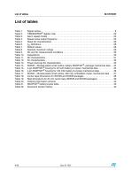
List of tables Table 1. Table 2. Table 3. Table 4. Table 5. Table 6. Table 7. Table 8. Table 9. Table 10. Table 11. Table 12. Table 13. Table 14. Table 15. Table 16. Table 17. Table 18. Table 19. Table 20. Table 21. Table 22. Signal names . . . . . . . . . . . . . . . . . . . . . . . . . . . . . . . . . . . . . . . . . . . . . . . . . . . . . . . . . . . . 8 TIMEKEEPER® register map . . . . . . . . . . . . . . . . . . . . . . . . . . . . . . . . . . . . . . . . . . . . . . . 20 Alarm repeat modes . . . . . . . . . . . . . . . . . . . . . . . . . . . . . . . . . . . . . . . . . . . . . . . . ....
Open the catalog to page 4
List of figures Figure 1. Figure 2. Figure 3. Figure 4. Figure 5. Figure 6. Figure 7. Figure 8. Figure 9. Figure 10. Figure 11. Figure 12. Figure 13. Figure 14. Figure 15. Figure 16. Figure 17. Figure 18. Figure 19. Figure 20. Figure 21. Figure 22. Figure 23. Figure 24. Figure 25. Figure 26. Figure 27. Logic diagram . . . . . . . . . . . . . . . . . . . . . . . . . . . . . . . . . . . . . . . . . . . . . . . . . . . . . . . . . . . . 7 28-pin SOIC connections . . . . . . . . . . . . . . . . . . . . . . . . . . . . . . . . . . . . . . . . . . . . . . . . . . . 8 28-pin, 300 mil SOIC connections...
Open the catalog to page 5
Description The M41ST85W is a combination serial real-time clock, microprocessor supervisor, and NVRAM supervisor. It is built in a low-power CMOS SRAM process and has a 64-byte memory space with 44 bytes of NVRAM and 20 memory-mapped RTC registers (see Table 2 on page 20). The RTC registers are configured in binary coded decimal (BCD) format. The M41ST85W combines a 400 kHz I2C serial RTC with an automatic backup battery switchover circuit for powering an external LPSRAM as well as the internal RTC. When power begins to fail, the switchover automatically connects to the backup battery to keep...
Open the catalog to page 6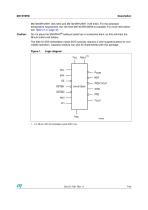
Description M4T28-BR12SH1 (48 mAh) and M4T32-BR12SH1 (120 mAh). For the extended temperature requirement, the 120 mAh M4T32-BR12SH6 is available. For more information, see Table 21 on page 40. Do not place the SNAPHAT® battery/crystal top in conductive foam, as this will drain the lithium button-cell battery. The 300 mil SOX embedded crystal SOIC typically requires a user-supplied battery for nonvolatile operation. Capacitor backup can also be implemented with this package. Figure 1. 1. For 28-pin, 300 mil embedded crystal SOIC only.
Open the catalog to page 7
Signal names Conditioned chip enable output External chip enable Interrupt/frequency test/out output (open drain) Power fail input Power fail output Reset output (open drain) Serial clock input Serial data input/output Square wave output Watchdog input Supply voltage Voltage output Battery supply voltage 1. For 28-pin, 300 mil embedded crystal SOIC only. VCC EX IRQ/FT/OUT VOUT NC NC PFI NC SCL NC RST NC SDA ECON
Open the catalog to page 8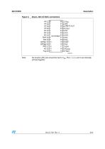
VCC EX IRQ/FT/OUT VOUT NC PFI SCL NC NC RST NC SDA ECON VBAT AI06370d No function (NF) pins should be tied to VSS. Pins 1, 2, 3, and 4 are internally shorted together.
Open the catalog to page 9
Figure 4. Block diagram REALTIME CLOCK SQUARE WAVE 1. Open drain output. 2. Crystal integrated into SOIC package for MX package option.
Open the catalog to page 10
Description Hardware hookup Regulator Unregulated Voltage Pushbutton Reset 1. Required for embedded crystal (MX) package only.
Open the catalog to page 11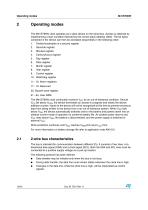
Operating modes Operating modes The M41ST85W clock operates as a slave device on the serial bus. Access is obtained by implementing a start condition followed by the correct slave address (D0h). The 64 bytes contained in the device can then be accessed sequentially in the following order: 1. Tenths/hundredths of a second register Seconds register Minutes register Century/hours register Date register Month register Year register Control register 10. Watchdog register 11 - 16. Alarm registers 17 - 19. Reserved 20. Square wave register 21 - 64. User RAM The M41ST85W clock continually monitors VCC...
Open the catalog to page 12All STMicroelectronics catalogs and technical brochures
 STGW30NC60KD
14 Pages
 STGB14NC60K STGD14NC60K
16 Pages
 HD1750FX
8 Pages
 TDA75610SLV
42 Pages
 TDA7391
13 Pages
 TDA7376B
15 Pages
 TDA7375V
15 Pages
 TDA2005
25 Pages
 L4989D, L4989MD
19 Pages
 L4938ED L4938EPD
20 Pages
 L4949ED-E L4949EP-E
19 Pages
 L4925
L492514 Pages
 FDA903U
80 Pages
 FDA803U
76 Pages
 FDA903D
82 Pages
 FDA803D
78 Pages
 BALF-SPI2-02D3
13 Pages
 LIS2DTW12
65 Pages
 VL53L0X
40 Pages
 LPS22HH
59 Pages
 Standard products offer overview
13 Pages
 M40SZ100W
20 Pages
 A1C15S12M3
17 Pages
 TSX923
32 Pages
 TS1851
24 Pages
 LMV321
17 Pages
 Serial real-time clock (RTC) ICs
16 Pages
 TDA2003LG
8 Pages
 HCF4541 Programmable Timer
10 Pages
 STA8058 GPS multi-chip module
14 Pages
 TDA7410ND Signal Processor
34 Pages
 TDA7410ND Signal Processor
34 Pages
 TSA1204 DUAL CHANNEL
31 Pages


Archived catalogs
 NEATSwitch
6 Pages
 Power MOSFETs for metering
2 Pages


- Single-pole switch
- Acceleration sensor
- Pressure probe
- Technology switch
- Signal amplifying integrated circuit
- Multipole switch
- Piezoelectric accelerometer
- Transceiver module
- Electronic filter
- Electromechanical switch
- Membrane pressure sensor
- Analog pressure sensor
- Rotary electric switch
- Triaxial acceleration sensor
- Power amplifying integrated circuit
- Distance sensor
- Diode
- STMicroelectronics transistor
- Low-pass electronic filter
- Absolute pressure sensor