- Catalogs
- STMicroelectronics
- LPS22HH
LPS22HH
1 /59Pages

LPS22HH
1 /59Pages
Catalog excerpts

LPS22HHHigh-performance MEMS nano pressure sensor: 260-1260 hPa absolute digital output barometer Datasheet - production data Features • 260 to 1260 hPa absolute pressure range • Current consumption down to 4 pA • Absolute pressure accuracy: 0.5 hPa • Low pressure sensor noise: 0.65 Pa • High-performance TCO: 0.65 Pa/°C • Embedded temperature compensation • 24-bit pressure data output • ODR from 1 Hz to 200 Hz • SPI, I2C or MIPI I3Csm interfaces • Embedded FIFO • Interrupt functions: Data-Ready, FIFO flags, pressure thresholds • Supply voltage: 1.7 to 3.6 V • High shock survivability: 22,000 g • Small and thin package • ECOPACK® lead-free compliant Applications • Altimeters and barometers for portable devices • GPS applications • Weather station equipment • Sport watches • e-cigarettes • Drones • Gas metering Description The LPS22HH is an ultra-compact piezoresistive absolute pressure sensor which functions as a digital output barometer. The device comprises a sensing element and an IC interface which communicates through FC, MIPI I3Csm or SPI from the sensing element to the application. The sensing element, which detects absolute pressure, consists of a suspended membrane manufactured using a dedicated process developed by ST. The LPS22HH is available in a full-mold, holed LGA package (HLGA). It is guaranteed to operate over a temperature range extending from -40 °C to +85 °C. The package is holed to allow external pressure to reach the sensing element. Table 1. Device summary This is information on a product in full production.
Open the catalog to page 1
Mechanical and electrical specifications . . . . . . . . . . . . . . . . . . . . . . . . 9 3.1 Communication interface characteristics . . . . . . . . . . . . . . . . . . . . . . . . . 11 3.3.1 3.3.2 SPI - serial peripheral interface . . . . . . . . . . . . . . . . . . . . . . . . . . . . . . . 11 I²C - inter-IC control interface . . . . . . . . . . . . . . . . . . . . . . . . . . . . . . . . 12 Absolute maximum ratings . . . . . . . . . . . . . . . . . . . . . . . . . . . . . . . . . . . . 13 Interpreting pressure readings . . . . . . . . . . . . . . . . . . . . . . . . . . . . . . . . . 15...
Open the catalog to page 2
I²C serial interface (CS = high) . . . . . . . . . . . . . . . . . . . . . . . . . . . . . . . . . 26 7.2.1 SPI read . . . . . . . . . . . . . . . . . . . . . . . . . . . . . . . . . . . . . . . . . . . . . . . . . 30 SPI read in 3-wire mode . . . . . . . . . . . . . . . . . . . . . . . . . . . . . . . . . . . . 32 MIPI I3CSM slave interface . . . . . . . . . . . . . . . . . . . . . . . . . . . . . . . . . . . . 33 7.4.1 MIPI I3CSM CCC supported commands . . . . . . . . . . . . . . . . . . . . . . . . 33
Open the catalog to page 3
HLGA-10L package information . . . . . . . . . . . . . . . . . . . . . . . . . . . . . . . . 55 HLGA-10L packing information . . . . . . . . . . . . . . . . . . . . . . . . . . . . . . . . 56
Open the catalog to page 4
List of tables Table 1. Table 2. Table 3. Table 4. Table 5. Table 6. Table 7. Table 8. Table 9. Table 10. Table 11. Table 12. Table 13. Table 14. Table 15. Table 16. Table 17. Table 18. Table 19. Table 20. Table 21. Table 22. Table 23. Table 24. Device summary . . . . . . . . . . . . . . . . . . . . . . . . . . . . . . . . . . . . . . . . . . . . . . . . . . . . . . . . . . 1 Pin description . . . . . . . . . . . . . . . . . . . . . . . . . . . . . . . . . . . . . . . . . . . . . . . . . . . . . . . . . . . 8 Pressure and temperature sensor characteristics . . . . . . . . . . . . . . . . . ....
Open the catalog to page 5
List of figures Figure 1. Figure 2. Figure 3. Figure 4. Figure 5. Figure 6. Figure 7. Figure 8. Figure 9. Figure 10. Figure 11. Figure 12. Figure 13. Figure 14. Figure 15. Figure 16. Figure 17. Figure 18. Figure 19. Figure 20. Figure 21. Figure 22. Figure 23. Figure 24. Figure 25. Figure 26. Figure 27. Figure 28. Figure 29. Device architecture block diagram . . . . . . . . . . . . . . . . . . . . . . . . . . . . . . . . . . . . . . . . . . . . 7 Digital logic . . . . . . . . . . . . . . . . . . . . . . . . . . . . . . . . . . . . . . . . . . . . . . . . . . . . . . . . . . . . . . 7 Pin connections...
Open the catalog to page 6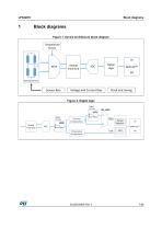
Sensor Bias
Open the catalog to page 7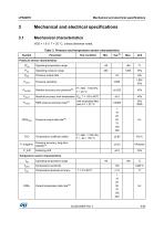
LPS22HH Mechanical and electrical specifications Table 3. Pressure and temperature sensor characteristics
Open the catalog to page 9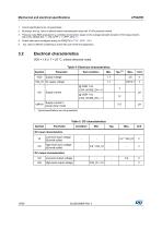
Mechanical and electrical specifications LPS22HH 1. Typical specifications are not guaranteed. 2. By design, the typ. value is defined based characterization data with 10 hPa pressure interval. 3. Pressure noise RMS evaluated in a controlled environment, based on the average standard deviation of 50 measurements with LOW_NOISE_EN = 1, EN_LPFP = 1, LPFP_CFG = 1. 4. Output data rate is configured acting on ODR[2:0] in CTRL_REG1 (10h). 5. Typ. value is defined considering a 5-year life cycle of the final application. 3.2 Electrical characteristics VDD = 1.8 V, T = 25 °C, unless otherwise noted....
Open the catalog to page 10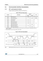
Mechanical and electrical specifications Communication interface characteristics SPI - serial peripheral interface Subject to general operating conditions for Vdd and TOP. Table 6. SPI slave timing values Value(1) Symbol SDI input setup time SDI input hold time SDO valid output time SDO output hold time SDO output disable time 1. Values are guaranteed at 10 MHz clock frequency for SPI with both 4 and 3 wires, based on characterization results, not tested in production. 2. Recommended to set max SPI clock 8 MHz to ≤50 Hz ODR. Figure 4. SPI slave timing diagram Measurement points are done at 0.2·Vdd_IO...
Open the catalog to page 11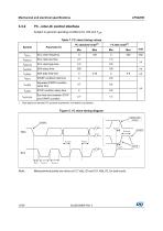
Mechanical and electrical specifications I²C - inter-IC control interface Subject to general operating conditions for Vdd and TOP. Table 7. I²C slave timing values Symbol f(SCL) Parameter (1) SCL clock frequency SCL clock high time SDA data hold time START condition hold time Repeated START condition setup time STOP condition setup time Bus free time between STOP and START condition 1. Data based on standard I²C protocol requirement, not tested in production. Figure 5. I²C slave timing diagram Measurement points are done at 0.2·Vdd_IO and 0.8·Vdd_IO, for both ports.
Open the catalog to page 12All STMicroelectronics catalogs and technical brochures
 STGW30NC60KD
14 Pages
 STGB14NC60K STGD14NC60K
16 Pages
 HD1750FX
8 Pages
 TDA75610SLV
42 Pages
 TDA7391
13 Pages
 TDA7376B
15 Pages
 TDA7375V
15 Pages
 TDA2005
25 Pages
 L4989D, L4989MD
19 Pages
 L4938ED L4938EPD
20 Pages
 L4949ED-E L4949EP-E
19 Pages
 L4925
L492514 Pages
 FDA903U
80 Pages
 FDA803U
76 Pages
 FDA903D
82 Pages
 FDA803D
78 Pages
 BALF-SPI2-02D3
13 Pages
 LIS2DTW12
65 Pages
 VL53L0X
40 Pages
 Standard products offer overview
13 Pages
 M40SZ100W
20 Pages
 A1C15S12M3
17 Pages
 TSX923
32 Pages
 TS1851
24 Pages
 LMV321
17 Pages
 Serial real-time clock (RTC) ICs
16 Pages
 TDA2003LG
8 Pages
 HCF4541 Programmable Timer
10 Pages
 STA8058 GPS multi-chip module
14 Pages
 TDA7410ND Signal Processor
34 Pages
 TDA7410ND Signal Processor
34 Pages
 TSA1204 DUAL CHANNEL
31 Pages


Archived catalogs
 NEATSwitch
6 Pages
 Power MOSFETs for metering
2 Pages


- Single-pole switch
- Acceleration sensor
- Technology switch
- Signal amplifying integrated circuit
- Multipole switch
- Piezoelectric accelerometer
- Transceiver module
- Electronic filter
- Electromechanical switch
- Analog pressure sensor
- Membrane pressure sensor
- Rotary electric switch
- Triaxial acceleration sensor
- Power amplifying integrated circuit
- Distance sensor
- Diode
- STMicroelectronics transistor
- Low-pass electronic filter