
- Catalogs
- STMicroelectronics
- LIS2DTW12

- Products
- Catalogs
- News & Trends
- Exhibitions
LIS2DTW12

LIS2DTW12
- Ultra-low power consumption: 50 nA in power-down mode, below 1 µA in active low-power mode.
- Very low noise: down to 1.3 mg RMS in low-power mode.
- Embedded temperature sensor with 0.8 °C typical accuracy.
- Multiple operating modes and bandwidths.
- Supply voltage range: 1.62 V to 3.6 V.
- ±2g/±4g/±8g/±16g full scale.
- High-speed I²C/SPI digital output interface.
- 16-bit accelerometer and 12-bit temperature data output.
- Self-test and 32-level FIFO buffer.
- High shock survivability: 10000 g.
- Fragile shipment tracking.
- Motion and temperature monitoring in battery-powered devices.
- Gesture recognition and gaming.
- Motion-activated functions and user interfaces.
- Display orientation and tap/double-tap recognition.
- Free-fall detection and smart power saving for handheld devices.
- Measurement range: ±2g to ±16g.
- Sensitivity varies with full scale and mode, e.g., 0.244 mg/digit at ±2g in high-performance mode.
- Noise density: 90 µg/√Hz in high-performance mode.
- Zero-g level offset accuracy: ±20 mg.
- Temperature accuracy: ±0.8 °C (0 °C to 70 °C), ±1.3 °C (-40 °C to +85 °C).
- Supply voltage: 1.62 V to 3.6 V.
- Current consumption varies with mode and ODR, e.g., 90 µA in high-performance mode.
- Digital input/output voltage levels specified for high and low states.
- SPI and I²C interfaces with specified timing values for standard and fast modes.
- SPI clock frequency up to 10 MHz, I²C clock frequency up to 400 kHz in fast mode.
- High-Performance Mode and four Low-Power Modes with different noise/power consumption trade-offs.
- Low-noise setting can be enabled or disabled, affecting operating mode characteristics.
- Supply voltage: -0.3 to 4.8 V.
- Operating temperature range: -40 to +85 °C.
- High shock survivability: 3000 g for 0.5 ms, 10000 g for 0.2 ms.
Catalog excerpts
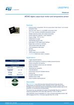
Product status link Features • Ultra-low power consumption: 50 nA in power-down mode, below 1 pA in active low-power mode • Very low noise: down to 1.3 mg RMS in low-power mode • 0.8 °C (typ. accuracy) embedded temperature sensor • Multiple operating modes with multiple bandwidths • Android stationary detection, motion detection • Supply voltage, 1.62 V to 3.6 V • High-speed I2C/SPI digital output interface • Single data conversion on demand • 16-bit accelerometer data output • 12-bit temperature data output • 10000 g high shock survivability • ECOPACK, RoHS and “Green” compliant • Fragile shipment tracking • Motion and temperature monitoring in battery-powered devices • Gesture recognition and gaming • Motion-activated functions and user interfaces • Display orientation • Tap/double-tap recognition • Free-fall detection • Smart power saving for handheld devices • Hearing aids • Portable healthcare devices • Wireless sensor nodes • Motion-enabled metering devices Description The LIS2DTW12 is an ultra-low-power high-performance three-axis linear accelerometer and temperature sensor belonging to the “femto” family which leverages on the robust and mature manufacturing processes already used for the production of micromachined accelerometers. The device has user-selectable full scales of ±2g/±4g/±8g/±16g and is capable of measuring accelerations with output data rates from 1.6 Hz to 1600 Hz. The LIS2DTW12 has an embedded 0.8 °C (typ. accuracy) temperature sensor with ODRs ranging from 50 to 1.6 Hz and resolution from 8 to 12 bits. DS12825 - Rev 3 - July 2019 For further information con
Open the catalog to page 1
The LIS2DTW12 has an integrated 32-level first-in, first-out (FIFO) buffer allowing the user to store data in order to limit intervention by the host processor. The embedded self-test capability allows the user to check the functioning of the sensor in the final application. The device has a dedicated internal engine to process motion and acceleration detection including free-fall, wakeup, highly configurable single/double-tap recognition, activity/inactivity, stationary/motion detection, portrait/landscape detection and 6D/4D orientation. The LIS2DTW12 is available in a small thin plastic land...
Open the catalog to page 2
LIS2DTW12 Block diagram and pin description Block diagram and pin description Block diagram Figure 1. Block diagram X+ Y+ CONTROL LOGIC TEMPERATURE SENSOR SELF TEST TRIMMING CIRCUITS CONTROL LOGIC & INTERRUPT GEN.
Open the catalog to page 3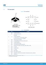
1.2 Pin description Figure 2. Pin connections 10 111 | 12 |T]2 (TOPVIEW) DIRECTION OF THE DETECTABLE ACCELERATIONS (BOTTOM VIEW) 1. SDO/SA0 and CS pins are internally pulled up. Refer to Table 2. Internal pull-up values (typ.) for SDO/SA0 and CS pins for the internal pull-up values (typ).
Open the catalog to page 4
Table 2. Internal pull-up values (typ.) for SDO/SA0 and CS pins
Open the catalog to page 5
LIS2DTW12 Mechanical and electrical specifications @ Vdd = 1.8 V, T = 25 °C unless otherwise noted. The product is factory calibrated at 1.8 V. The operational power supply range is from 1.62 V to 3.6 V. Table 3. Mechanical characteristics 1. Typical specifications are not guaranteed. 2. Noise density is the same for all ODRs. Low-noise setting enabled. 3. RMS noise is the same for all ODRs. Low-noise setting enabled. 4. Values after factory calibration test and trimming.
Open the catalog to page 6
Table 4. Electrical characteristics 1. Typical specifications are not guaranteed. 2. It is possible to remove Vdd maintaining Vdd_IO without blocking the communication busses. In this condition the measurement chain is powered off. 3. Low-noise setting disabled. 4. Low-Power Mode 1. Low-noise setting disabled. 5. 4 mA is the maximum driving capability, ie. the maximum DC current that can be sourced/sunk by the digital pad in order to guarantee the correct digital output voltage levels Vqh and Vql.
Open the catalog to page 7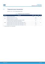
LIS2DTW12 Temperature sensor characteristics @ Vdd = 1.8 V, T = 25 °C unless otherwise noted. Table 5. Temperature sensor characteristics 1. Typical specifications are not guaranteed.
Open the catalog to page 8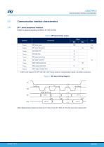
LIS2DTW12 Communication interface characteristics 2.4.1 SPI - serial peripheral interface Subject to general operating conditions for Vdd and Top. Table 6. SPI slave timing values Note: Measurement points are done at 0.2Vdd_IO and 0.8Vdd_IO, for both input and output ports.
Open the catalog to page 9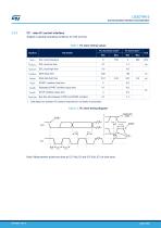
LIS2DTW12 Communication interface characteristics Table 7. PC slave timing values 1. Data based on standard I2C protocol requirement, not tested in production. Figure 4. PC slave timing diagram Note: Measurement points are done at 0.2-VddJO and 0.8-VddJO, for both ports. page 10/65
Open the catalog to page 10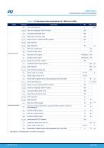
LIS2DTW12Communication interface characteristics Table 8. PC high-speed mode specifications at 1 MHz and 3.4 MHz
Open the catalog to page 11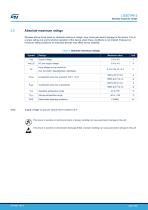
LIS2DTW12 Absolute maximum ratings 2.5 Absolute maximum ratings Stresses above those listed as “absolute maximum ratings” may cause permanent damage to the device. This is a stress rating only and functional operation of the device under these conditions is not implied. Exposure to maximum rating conditions for extended periods may affect device reliability. Table 9. Absolute maximum ratings This device is sensitive to mechanical shock, improper handling can cause permanent damage to the part. This device is sensitive to electrostatic discharge (ESD), improper handling can cause permanent damage...
Open the catalog to page 12
Sensitivity Sensitivity describes the gain of the sensor and can be determined by applying 1 g acceleration to it. As the sensor can measure DC accelerations this can be done easily by pointing the axis of interest towards the center of the Earth, noting the output value, rotating the sensor by 180 degrees (pointing to the sky) and noting the output value again. By doing so, ±1 g acceleration is applied to the sensor. Subtracting the larger output value from the smaller one, and dividing the result by 2, leads to the actual sensitivity of the sensor. This value changes very little over temperature...
Open the catalog to page 13All STMicroelectronics catalogs and technical brochures
 STGW30NC60KD
14 Pages
 STGB14NC60K STGD14NC60K
16 Pages
 HD1750FX
8 Pages
 TDA75610SLV
42 Pages
 TDA7391
13 Pages
 TDA7376B
15 Pages
 TDA7375V
15 Pages
 TDA2005
25 Pages
 L4989D, L4989MD
19 Pages
 L4938ED L4938EPD
20 Pages
 L4949ED-E L4949EP-E
19 Pages
 L4925
L492514 Pages
 FDA903U
80 Pages
 FDA803U
76 Pages
 FDA903D
82 Pages
 FDA803D
78 Pages
 BALF-SPI2-02D3
13 Pages
 VL53L0X
40 Pages
 LPS22HH
59 Pages
 Standard products offer overview
13 Pages
 M40SZ100W
20 Pages
 A1C15S12M3
17 Pages
 TSX923
32 Pages
 TS1851
24 Pages
 LMV321
17 Pages
 Serial real-time clock (RTC) ICs
16 Pages
 TDA2003LG
8 Pages
 HCF4541 Programmable Timer
10 Pages
 STA8058 GPS multi-chip module
14 Pages
 TDA7410ND Signal Processor
34 Pages
 TDA7410ND Signal Processor
34 Pages
 TSA1204 DUAL CHANNEL
31 Pages


Archived catalogs
 NEATSwitch
6 Pages
 Power MOSFETs for metering
2 Pages


- Single-pole switch
- Pressure probe
- Technology switch
- Piezoelectric accelerometer
- Signal amplifying integrated circuit
- Multipole switch
- Transceiver module
- Electronic filter
- Electromechanical switch
- Membrane pressure sensor
- Rotary electric switch
- Analog pressure sensor
- Triaxial acceleration sensor
- Power amplifying integrated circuit
- Distance sensor
- Diode
- STMicroelectronics transistor
- Low-pass electronic filter
- Absolute pressure sensor