
- Catalogs
- STMicroelectronics
- 32-bit Power Architecture® based MCU with 1088 KB Flash memory and 80 KB RAM for safety applications

- Products
- Catalogs
- News & Trends
- Exhibitions
32-bit Power Architecture® based MCU with 1088 KB Flash memory and 80 KB RAM for safety applications

32-bit Power Architecture® based MCU with 1088 KB Flash memory and 80 KB RAM for safety applications
This document is a comprehensive datasheet for the RPC56AP60x and RPC56AP54x series of microcontrollers, designed for safety applications and based on a 32-bit Power Architecture®. It provides detailed specifications, features, and operational guidelines.
- 64 MHz, 32-bit CPU core compliant with Power Architecture®.
- Up to 1088 KB Flash memory and 80 KB RAM with ECC for safety.
- Fail-safe protection mechanisms including ECC, safety port, and non-maskable interrupts.
- Various communication interfaces including LINFlex, DSPI, FlexCAN, and FlexRay.
- 10-bit A/D converter with 27 input channels and fast conversion time.
- Aerospace and defense features for enhanced durability and traceability.
The microcontroller features a high-performance e200z0h core processor, on-chip Flash memory with ECC, and on-chip SRAM with ECC. It supports a variety of memory management and protection features to ensure data integrity and system reliability.
The device includes multiple peripherals such as general-purpose I/Os, eTimer units, and a 16-channel eDMA controller. It supports various communication protocols through LINFlex, DSPI, FlexCAN, and FlexRay modules.
The document outlines the electrical characteristics, including absolute maximum ratings, recommended operating conditions, and thermal characteristics. It also details the power management features and the electrical specifications of the voltage regulator and monitor.
The microcontrollers are available in LQFP100 and LQFP144 packages, with detailed mechanical outlines provided. The document also includes information on ECOPACK® compliance and package characteristics.
Details on ordering the microcontrollers are provided, including part numbers and configuration options.
This datasheet serves as a comprehensive guide for the RPC56AP60x and RPC56AP54x microcontrollers, offering detailed technical specifications and operational guidelines for developers and engineers working on safety-critical applications.
The RPC56xP54/60 series is a 32-bit system-on-chip (SoC) microcontroller family designed for high performance and low power consumption. It operates up to 64 MHz and is supported by a robust development infrastructure, including software drivers and operating systems.
The document includes a comparison table of different members of the RPC56xP54/60 family, detailing features such as code flash memory, SRAM, processor core, and various modules like FlexRay and DSPI.
A block diagram of the RPC56xP54/60 MCU is provided, along with a summary of the functions of each block. Key components include the analog-to-digital converter (ADC), clock generation module, controller area network (FlexCAN), and enhanced direct memory access (eDMA).
- High Performance e200z0h Core Processor: Features a 32-bit Power Architecture CPU with a 4-stage pipeline, Harvard architecture, and variable length encoding for efficient code size and performance.
- Crossbar Switch (XBAR): Supports simultaneous connections between master and slave ports, allowing concurrent transactions and prioritizing requests through arbitration logic.
- Enhanced Direct Memory Access (eDMA): Capable of complex data movements with 16 programmable channels, supporting various transfer sizes and DMA requests.
- On-chip Flash Memory with ECC: Provides up to 1024 KB of programmable memory with features like prefetch buffers, read/write protections, and ECC for data integrity.
- On-chip SRAM with ECC: Offers up to 80 KB of general-purpose memory with support for various write operations and ECC for error correction.
- Interrupt Controller (INTC): Manages priority-based scheduling of interrupts, supporting real-time systems with configurable priorities and unique vectors for each interrupt source.
- System Clocks and Clock Generation: Includes features like lock detection, programmable output clock dividers, and internal oscillators for stable clock generation.
- Frequency Modulated Phase-Locked Loop (FMPLL): Generates high-speed system clocks with programmable modulation and self-clocked mode operation.
- Periodic Interrupt Timer (PIT) and System Timer Module (STM): Provide general-purpose interrupt timers and compare channels for task scheduling and interrupt generation.
- Software Watchdog Timer (SWT): Ensures program flow control with features like windowed watchdog and pseudorandom key generation.
- Fault Collection and Control Unit (FCCU): Offers independent fault reporting and configurable fault control for system reliability.
- System Integration Unit (SIUL): Manages MCU pad configuration, GPIO control, and peripheral multiplexing with features like digital input filtering and pin value readback.
- Boot Modes: Supports booting from internal flash memory or via serial links like FlexCAN or LINFlex, with a censorship scheme for flash memory protection.
- Boot Assist Module (BAM): Facilitates serial bootloading and password protection for secure access to non-volatile memory.
- Error Correction Status Module (ECSM): Provides ECC error reporting and injection for flash memory and SRAM.
- FlexCAN: Implements the CAN protocol for reliable vehicle serial data communication.
The FlexCAN module supports the CAN protocol Version 2.0B, offering 32 message buffers configurable for Rx or Tx, with a programmable bit rate up to 1 Mbit/s. It includes features like loop-back mode, maskable interrupts, and high immunity to EMI.
This module acts as a second CAN controller with a bit rate up to 7.5 Mb at 60 MHz CPU clock, providing identical features to the FlexCAN module.
Implements FlexRay Protocol Specification 2.1, supporting 64 configurable message buffers and dual or single channel operation with data rates up to 10 Mbit/s.
Supports LIN Master and Slave modes, and UART mode, with features like autonomous LIN frame handling, error detection, and interrupt-driven operation.
Provides synchronous serial communication with features like full duplex transfers, programmable master bit rates, and up to 28 chip select lines.
Includes two modules with six 16-bit timers each, offering features like input capture, output compare, and quadrature decode capabilities.
Features a 10-bit resolution ADC with a conversion time of less than 1 μs, supporting 27 input channels and various operating modes.
Facilitates automatic ADC conversion requests with minimized CPU load, supporting up to eight independent triggers.
Supports concurrent CRC computation with three contexts and zero-wait states, using hard-wired polynomials.
Provides real-time development support compliant with IEEE-ISTO 5001-2003, offering features like static debug and program trace messaging.
Enables chip testing and connectivity with a TAP interface, supporting various IEEE-defined instructions.
Regulates external voltage down to 1.2 V for core logic, with low voltage detection features.
Includes detailed pinout diagrams for LQFP176 and LQFP144 packages, noting that LQFP176 is for software development only.
- FlexCAN: Operates in loop-back mode with a message sending period of 580 μs. Consumption is calculated as 21.6 * fperiph to 28.1 * fperiph μA.
- SCI (LINFlex): In LIN mode with a baud rate of 115.2 Kbyte/s, consumption ranges from 10.8 * fperiph to 14.1 * fperiph.
- SPI (DSPI): At a baud rate of 2 Mbit/s, with transmission every 8 μs, consumption is 4.8 * fperiph to 6.3 * fperiph.
- ADC: For continuous conversion, consumption is 120 * fperiph to 156 * fperiph on VDD_HV_REG and 0.005 * fperiph + 2.8 to 0.007 * fperiph + 3.4 mA on VDD_HV_ADC.
- eTimer: Generates PWM signals at 10kHz with a static consumption of 1.8 to 2.4 mA.
- FlexRay: Static consumption is 4.2 * fperiph to 5.5 * fperiph μA.
- Dynamic I/O current varies based on configuration (SLOW, MEDIUM, FAST) and supply voltage (3.3V or 5.0V).
- Root medium square I/O current is specified for different configurations and frequencies.
- Main oscillator frequency ranges from 4 to 40 MHz with specific transconductance and start-up times depending on voltage levels.
- FMPLL characteristics include input clock specifications and PLL reference frequency ranges.
- The ADC is a 10-bit SAR type, requiring low AC impedance on analog input pins for accuracy.
- Input impedance and ADC accuracy are maintained by using capacitors and RC filters to manage noise and charge sharing effects.
- External circuit design must consider resistive paths and filter design to ensure accurate ADC readings.
- Anti-aliasing filters are recommended to match the Nyquist theorem requirements for conversion rates.
Catalog excerpts

RPC56AP60x, RPC56AP54x RPC560P60x, RPC560P54x 32-bit Power Architecture® based MCU with 1088 KB Flash memory and 80 KB RAM for safety applications Datasheet - production data – Quadrature decode with rotation direction flag – Double buffer input capture and output compare LQFP100 14 x 14 mm Features 64 MHz, single issue, 32-bit CPU core complex (e200z0h) – Compliant with Power Architecture® embedded category – Variable Length Encoding (VLE) Memory organizazion – Up to 1024 KB on-chip code Flash memory with additional 64 KB for EEPROM emulation (data flash), with ECC, with erase/program controller – Up to 80 KB on-chip SRAM with ECC Fail safe protection – ECC protection on system SRAM and Flash – Safety port – SWT with servicing sequence pseudorandom generator – Power management – Non-maskable interrupt for both cores – Fault collection and control unit (FCCU) – Safe mode of system-on-chip (SoC) – Register protection scheme Nexus® L2+ interface Single 3.3 V or 5 V supply for I/Os and ADC 2 on-platform peripherals set with 2 INTC 16-channel eDMA controller with multiple transfer request sources General purpose I/Os 2 general purpose eTimer units – 6 timers, each with up/down count capabilities – 16-bit resolution, cascadable counters January 2015 This is information on a product in full production. Communications interfaces – 2 LINFlex modules (LIN 2.1, 1 × Master/Slave, 1 × Master Only) – 5 DSPI modules with automatic chip select generation – 2 FlexCAN interfaces (2.0B Active) with 32 message buffers – 1 Safety port based on FlexCAN; usable as third CAN when not used as safety port – 1 FlexRay™ module (V2.1) with dual or single channel, 64 message buffers and up to 10 Mbit/s 2 CRC units with three contexts and 3 hardwired polynomials 10-bit A/D converter – 27 input channels and pre-sampling feature – Conversion time < 1 μs including sampling time at full precision – Programmable cross triggering unit (CTU) – 4 analog watchdog with interrupt capability On-chip CAN/UART Bootstrap loader with boot assist module (BAM) Ambient temperature ranges: –40 to 125 °C Aerospace and Defense features – Dedicated traceability and part marking – Production parts approval documents available – Adapted Extended life time and obsolescence management – Extended Product Change Notification process – Designed and manufactured to meet sub ppm quality goals – Advanced mold and frame designs for Superior resilience to harsh environment (acceleration, EMI, thermal, humidity) – Single Fabrication, Assembly and Test site – Dual internal production source capability
Open the catalog to page 1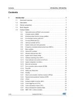
Crossbar switch (XBAR) . . . . . . . . . . . . . . . . . . . . . . . . . . . . . . . . . . . . 13 Enhanced direct memory access (eDMA) . . . . . . . . . . . . . . . . . . . . . . . 14 On-chip flash memory with ECC . . . . . . . . . . . . . . . . . . . . . . . . . . . . . . 14 On-chip SRAM with ECC . . . . . . . . . . . . . . . . . . . . . . . . . . . . . . . . . . . . 15 Interrupt controller (INTC) . . . . . . . . . . . . . . . . . . . . . . . . . . . . . . . . . . . 15 System clocks and clock generation . . . . . . . . . . . . . . . . . . . . . . . . . . . 16 Frequency modulated phase-locked...
Open the catalog to page 2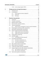
Contents On-chip voltage regulator (VREG) . . . . . . . . . . . . . . . . . . . . . . . . . . . . . 26 Package pinouts and signal descriptions . . . . . . . . . . . . . . . . . . . . . . . 27 2.1 Power supply and reference voltage pins . . . . . . . . . . . . . . . . . . . . . . . 29 Pin muxing . . . . . . . . . . . . . . . . . . . . . . . . . . . . . . . . . . . . . . . . . . . . . . . 33 Absolute maximum ratings . . . . . . . . . . . . . . . . . . . . . . . . . . . . . . . . . . . . 49 Recommended operating conditions . . . . . . . . . . . . . . . . . . . . . . . . . . . . 51 General notes...
Open the catalog to page 3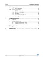
IEEE 1149.1 interface timing . . . . . . . . . . . . . . . . . . . . . . . . . . . . . . . . . 86 External interrupt timing (IRQ pin) . . . . . . . . . . . . . . . . . . . . . . . . . . . . . 90 Package mechanical data . . . . . . . . . . . . . . . . . . . . . . . . . . . . . . . . . . . . 97 4.2.1 LQFP144 mechanical outline drawing . . . . . . . . . . . . . . . . . . . . . . . . . . 97 LQFP100 mechanical outline drawing . . . . . . . . . . . . . . . . . . . . . . . . . . 99
Open the catalog to page 4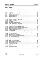
List of tables Table 1. Table 2. Table 3. Table 4. Table 5. Table 6. Table 7. Table 8. Table 9. Table 10. Table 11. Table 12. Table 13. Table 14. Table 15. Table 16. Table 17. Table 18. Table 19. Table 20. Table 21. Table 22. Table 23. Table 24. Table 25. Table 26. Table 27. Table 28. Table 29. Table 30. Table 31. Table 32. Table 33. Table 34. Table 35. Table 36. Table 37. Table 38. Table 39. Table 40. Table 41. Table 42. Table 43. RPC56xP54/60 device comparison . . . . . . . . . . . . . . . . . . . . . . . . . . . . . . . . . . . . . . . . . . . 7 RPC56xP54/60 device configuration difference...
Open the catalog to page 5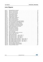
List of figures Figure 1. Figure 2. Figure 3. Figure 4. Figure 5. Figure 6. Figure 7. Figure 8. Figure 9. Figure 10. Figure 11. Figure 12. Figure 13. Figure 14. Figure 15. Figure 16. Figure 17. Figure 18. Figure 19. Figure 20. Figure 21. Figure 22. Figure 23. Figure 24. Figure 25. Figure 26. Figure 27. Figure 28. Figure 29. Figure 30. Figure 31. Figure 32. Figure 33. Figure 34. Figure 35. Figure 36. Figure 37. Figure 38. Figure 39. Figure 40. RPC56xP54/60 block diagram . . . . . . . . . . . . . . . . . . . . . . . . . . . . . . . . . . . . . . . . . . . . . . 10 LQFP176 pinout (top view) . ....
Open the catalog to page 6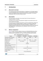
Document overview This document provides electrical specifications, pin assignments, and package diagrams for the RPC56xP54/60 series of microcontroller units (MCUs). It also describes the device features and highlights important electrical and physical characteristics. For functional characteristics, refer to the device reference manual. Description This 32-bit system-on-chip (SoC) microcontroller family is the latest achievement in integrated application controllers. This family is one of a series of next-generation integrated microcontrollers based on the Power Architecture technology. The...
Open the catalog to page 7All STMicroelectronics catalogs and technical brochures
 STGW30NC60KD
14 Pages
 STGB14NC60K STGD14NC60K
16 Pages
 HD1750FX
8 Pages
 TDA75610SLV
42 Pages
 TDA7391
13 Pages
 TDA7376B
15 Pages
 TDA7375V
15 Pages
 TDA2005
25 Pages
 L4989D, L4989MD
19 Pages
 L4938ED L4938EPD
20 Pages
 L4949ED-E L4949EP-E
19 Pages
 L4925
L492514 Pages
 FDA903U
80 Pages
 FDA803U
76 Pages
 FDA903D
82 Pages
 FDA803D
78 Pages
 BALF-SPI2-02D3
13 Pages
 LIS2DTW12
65 Pages
 VL53L0X
40 Pages
 LPS22HH
59 Pages
 Standard products offer overview
13 Pages
 M40SZ100W
20 Pages
 A1C15S12M3
17 Pages
 TSX923
32 Pages
 TS1851
24 Pages
 LMV321
17 Pages
 Serial real-time clock (RTC) ICs
16 Pages
 TDA2003LG
8 Pages
 HCF4541 Programmable Timer
10 Pages
 STA8058 GPS multi-chip module
14 Pages
 TDA7410ND Signal Processor
34 Pages
 TDA7410ND Signal Processor
34 Pages
 TSA1204 DUAL CHANNEL
31 Pages


Archived catalogs
 NEATSwitch
6 Pages
 Power MOSFETs for metering
2 Pages


- Single-pole switch
- Acceleration sensor
- Pressure probe
- Technology switch
- Piezoelectric accelerometer
- Multipole switch
- Signal amplifying integrated circuit
- Transceiver module
- Electronic filter
- Electromechanical switch
- Membrane pressure sensor
- Rotary electric switch
- Analog pressure sensor
- Triaxial acceleration sensor
- Power amplifying integrated circuit
- Distance sensor
- Diode
- STMicroelectronics transistor
- Low-pass electronic filter
- Absolute pressure sensor