

Shaft gearboxes - Shaft mounted gearboxes and geared motors

Shaft gearboxes - Shaft mounted gearboxes and geared motors
Catalog excerpts

CT17IGBD2 E1 1.0 RIDUTTORI - MOTORIDUTTORI PARALLELI - PENDOLARI SHAFT GEARBOXES - SHAFT MOUNTED GEARBOXES AND GEARED MOTORS FLACH-UND AUFSTECKGETRIEBE UND-GETRIEBEMOTOREN PM PR, PC Pag. Page Seite 1.1 Caratteristiche tecniche Technical characteristics Technische Eigenschaften E2 1.2 Designazione Designation Bezeichnungen E2 1.3 Versioni Versions Ausführungen E5 1.4 Lubrificazione Lubrication Schmierung E6 1.5 Carichi radiali e assiali Axial and overhung loads Radiale und Axiale Belastungen E7 1.6 Prestazioni riduttori Gearboxes performances Leistungen der Getriebe E8 1.7 Prestazioni motoriduttori Gearmotors performances Leistungen der Getriebemotoren E13 1.8 Dimensioni Dimensions Abmessungen E20 1.9 Accessori Accessories Zubehör E33 1.10 Linguette Keys Paßfedern E34 E
Open the catalog to page 1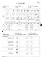
CT17IGBD2 E3 Grandezza Size Größe [*3] Albero forato Shaft with keyway Holwelle mit Paßfedernut Albero forato con calettatore Hollow shaft with shrink disc Holwelle mit Schrupmfscheibe Sporgente Integrale Output shaft Holwelle mit Wellenende Bisporgente integrale Double output shaft Holwelle mit Doppeltem Wellenende Sporgente Scanalato Splined output shaft Abtriebswelle mit Keilende Bisporgente integrale Scanalato Double splined shaft Doppelseitig verzahnte Welle Albero forato Scanalato Splined hollow shaft Verzahnte Hohlwelle Flangia brocciata Broached flange Geräumtem Flansch Flangia brocciata...
Open the catalog to page 3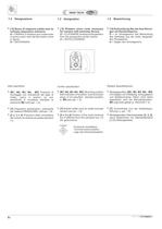
E4 • [M1, M2, M3, M4, M5] Posizioni di montaggio con indicazione dei tappi di livello, carico e scarico; se non specificato si considera standard la posizione M6 (vedi par. 1.4). • [T] Dispositivo antivibrante ( solamente per versione PENDOLARE :vedi par. 1.9). • [2 o 3 o 4] Posizione della morsettiera del motore se diversa da quella standard (1). • Montageposition [M1, M2, M3, M4, M5] mit Angabe von Entlüftung, Schaugläsern und Ablaßschraube. Wenn nicht näher spezifiziert, wird die Standardposition M6 zugrunde gelegt (s. Abschnitt 1.4). • [T] Gummihülse (nur bei Aufsteckausführung: s. par. 1.9)....
Open the catalog to page 4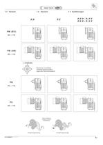
CT17IGBD2 E5 1.3 Versioni 1.3 Versions 1.3 Ausführungen P.F P.P P - P. P F P.F P - P. F F P.P PC. Posizione morsettiera Terminal board position Lage des Klemmenkastens 63 — 112 PM. (IEC) 63 — 112 PM. (kW) 63 — 112 PR. 63 — 112 Senso di rotazione Direction of rotation Drehrichtung 2 stadi/stages/stufig 3 stadi/stages/stufig CT17IGBD2.1.
Open the catalog to page 5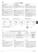
E6 1.4 Lubrificazione 1.4 Lubrication 1.4 Schmierung Carico / Breather plug / Einfüll-u. Entlüftungsschraube Livello / Level plug / Schauglas Scarico / Drain plug / Ablaßschraube Tab. 4.2 Posizioni di montaggio Mounting positions Montagepositionen M1 M2 M3 M4 M5 M6 Generalità Si consiglia l’uso di oli a base sintetica. (Vedere a tale proposito le indicazioni riportate nel capitolo A, paragrafo 1.6). Nella Tab. 4.2 sono riportati i quantitativi di olio necessari per il corretto funzionamento dei riduttori. Prescrizioni in fase d’ordine e stato di fornitura I riduttori della grandezza 63, 71 è...
Open the catalog to page 6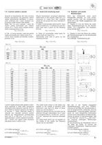
CT17IGBD2 E7 Tab. 4.4 Tab. 4.3 In Table 4.4 permissible radial loads for output shaft are listed (Fr2). Permissible axial load is given by the following formula: Fa2 = 0.2 x Fr2 In Tabelle 4.4 sind die Werte der zulässigen Radialbelastungen für die Abtriebswelle (Fr2) angegeben. Als zulässige Axialbelastung gilt: Fa2 = 0.2 x Fr2 In Tab. 4.4 sono riportati i valori dei carichi radiali ammissibili per l’albero lento (Fr2) . Come carico assiale ammissibile contemporaneo si ha: Fa2 = 0.2 x Fr2 The radial loads shown in the tables are applied on the middle of standard shaft extensions (see fig.8.14)....
Open the catalog to page 7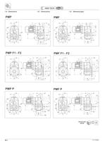
E20 CT17IGBD2 1.8 Dimensioni 1.8 Dimensions 1.8 Abmessungen A Y S N O hP C K P1 n2 n1 h1 h H B L3 V D R G F U Z PMP F1 - F2 PMF F1 - F2 A Y a S N O hP C K P1 n2 n1 h1 h H f bB I P V D R G F U Z h2 A Y Vp Rp S N D O hP C K p1 n2 n1 h1 h Gp Fp H B L4 45° 45° 30° 30° Up PMP P PMF P A Y a Vp Rp S N D O hP C K p1 n2 n1 h1 h Gp Fp H f bB I h2 45° 45° 30° 30° Up Pp Y S c1 K C n2 h1 h Fp H B L2 A Vp Rp N D O hP n1 45° 45° 30° 30° PMP PMF A Y a Vp Rp S N D O hP c1 i1 K C n2 n1 h1 h Fp H f bB I h2 45° 45° 30° 30° 2D 3D DownLoad 2D/3D Z4
Open the catalog to page 20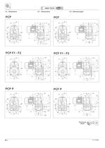
E22 CT17IGBD2 A S N O hP C K P1 n2 n1 h1 h H B L3 V D R G F U Z Y PCP F1 - F2 PCF F1 - F2 1.8 Dimensioni 1.8 Dimensions 1.8 Abmessungen A a S N O hP C K P1 n2 n1 h1 h H f bB I P V D R G F U Z h2 Y A Vp Rp S N D O hP C K p1 n2 n1 h1 h Gp Fp H B L4 45° 45° 30° 30° Up Y PCP P PCF P A a Vp Rp S N D O hP C K p1 n2 n1 h1 h Gp Fp H f bB I h2 45° 45° 30° 30° Up Pp Y A Vp Rp S N D O hP c1 K C n2 n1 h1 h Fp H B L2 45° 45° 30° 30° Y PCP PCF A a Vp Rp S N D O hP c1 i1 K C n2 n1 h1 h Fp H f bB I h2 45° 45° 30° 30° Y 2D 3D DownLoad 2D/3D Z4
Open the catalog to page 22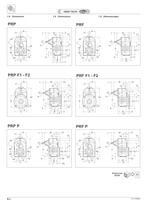
E24 CT17IGBD2 1.8 Dimensioni 1.8 Dimensions 1.8 Abmessungen A d m S N O hP C L M P1 n2 n1 h1 h H B L3 V D R G F U Z PRP F1 - F2 PRF F1 - F2 A a d m S N O hP C L M P1 n2 n1 h1 h H fbB I P V D R G F U Z h2 A d m Vp Rp S N D O hP C L M p1 n2 n1 h1 h Gp Fp H B L4 45° 45° 30° 30° Up PRP P PRF P A a d m Vp Rp S N D O hP C L M p1 n2 n1 h1 h Gp Fp H fbB I h2 45° 45° 30° 30° Up Pp A d m Vp Rp S N D O hP c1 M C n2 n1 L h1 h Fp H B L2 45° 45° 30° 30° PRP PRF A a d m Vp Rp S N D O hP c1 i1 M C n2 n1 L h1 h Fp H fbB I h2 45° 45° 30° 30° 2D 3D DownLoad 2D/3D Z4
Open the catalog to page 24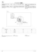
E26 CT17IGBD2 PARTICOLARE DEI FORI “t“ NELLA FLANGIA P Per il fissaggio al riduttore con i fori “Vp” considerare la lunghezza delle viti adeguate, e che la quota “yt” non è filettata (vedi disegno). Bei Verwendung des P-Flansches ist zu beachten, daß sich die Gewinde im Getriebegehäuse befinden und daß Maß “yt” kein Gewinde besitzt. Details siehe Zeichnung. DETAIL “t” BEI VERWENDUNG DES P-FLANSCHES P.P - P.F Vp xt yt 63 N°6 M6 12 11,5 71 N°6 M8 14 11 90 N°6 M12 18 12 112 N°6 M14 21 14 fissaggio utente Befestugung von benutzer assembly customer xt Vp yt When P-flange is used please consider that...
Open the catalog to page 26All Stm Spa catalogs and technical brochures
 LONG PARALLEL SHAFT MOUNTED PL
46 Pages
 SKEW BEVEL HELICAL S
20 Pages
 BEVEL HELICAL O
76 Pages
 IN-LINE A
54 Pages
 SINGLE STAGE AR/1
54 Pages
Archived catalogs
 Industrial gearboxes
52 Pages
 Worm gearboxes
58 Pages
 Agriculture sector gearboxes
62 Pages
 Torque limiter
14 Pages
 Mechanical variators
12 Pages
 Right angle
34 Pages
 Electric motors & Inverters
81 Pages
 In-line gearboxes
50 Pages
- Electromotor
- Alternating current motor
- Asynchronous motor
- Planetary gearbox
- Three-phase motor
- Right angle gearhead
- Compact gearhead
- Gear train gear reducer
- Gearbox for industrial applications
- Transmission gearhead
- 380 V motor
- Single-stage gearhead
- Shaft gearhead
- Helical gear gearhead
- Machines gearbox
- 400 V motor
- 48 V motor
- Clamp gearbox
- Electric motor gearhead
- Bevel gearhead