

In-line gearboxes

In-line gearboxes
The gearboxes are constructed with a robust monolithic structure to support heavy loads. They come in various sizes and types, each designated for specific applications.
The document details the designation system for gearboxes and motors, including size, type, and mounting options. Certain versions, such as AC 35, 41, 45, 100, 120, and AR 25, 35, 41, 45, are unavailable.
Synthetic oil is recommended for lubrication. Gearboxes of sizes 32, 40, 50, 60 are supplied with ISO 320 viscosity synthetic oil, while sizes 80 and 100 require oil lubrication but are delivered without lubricant. Mounting positions must be specified when ordering.
The document specifies permissible radial and axial load values for input and output shafts, with axial load calculated as 0.2 times the radial load. Tables provide specific load values based on gearbox size and speed.
Performance tables offer detailed specifications on gearbox and gearmotor performance. Dimensions and key specifications are provided for various gearbox sizes.
This document provides technical specifications and guidelines for shaft/flange combinations, focusing on B5 and B14 standards. It includes detailed dimensions, configurations, and installation recommendations.
The document outlines dimensions for standard B5 and B14 shaft/flange combinations, referred to as cMF and cMP dimensions. For custom combinations, it advises contacting the technical department for specific measurements.
The standard configuration for flange holes is at a 45° angle to the axles, resembling an 'x' pattern. For B14 flanges marked with a specific symbol, the holes align with the axles in a '+' pattern. A sketch is provided to assist in choosing the terminal board position, with position 5 being standard.
Tables include detailed measurements for various components, such as gearbox and flange dimensions. Key parameters include hole sizes, distances between holes, and overall component dimensions.
For non-standard configurations or specific requirements, consulting the technical department is recommended. The document emphasizes verifying motor terminal board dimensions for proper alignment and fit.
This technical document serves as a comprehensive guide for understanding and implementing standard and custom shaft/flange combinations, providing essential data and recommendations for proper installation and functionality.
Catalog excerpts
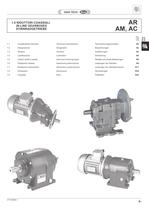
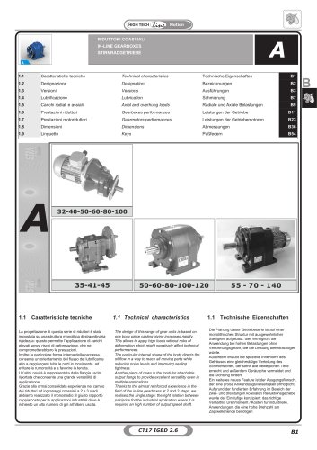
CT17IGBD2.1 B1 B 1.0 RIDUTTORI COASSIALI IN-LINE GEARBOXES STIRNRADGETRIEBE AR AM, AC 1.1 Caratteristiche tecniche Technical characteristics Technische Eigenschaften B2 1.2 Designazione Designation Bezeichnungen B2 1.3 Versioni Versions Ausführungen B3 1.4 Lubrificazione Lubrication Schmierung B4 1.5 Carichi radiali e assiali Axial and overhung loads Radiale und Axiale Belastungen B6 1.6 Prestazioni riduttori Gearboxes performances Leistungen der Getriebe B8 1.7 Prestazioni motoriduttori Gearmotors performances Leistungen der Getriebemotoren B17 1.8 Dimensioni Dimensions Abmessungen B30 1.9 Linguette Keys Paßfedern B42 Pag. Page Seite
Open the catalog to page 1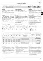
CT17IGBD2.1 B5 B Carico / Breather plug / Nachfüllen - Entlüftung Livello / Level plug / Pegel Scarico / Drain plug / Auslauf 1.4 Lubrificazione 1.4 Lubrication 1.4 Schmierung Posizioni di montaggio Mounting positions Montagepositionen M1 M2 M3 M4 M5 M6 Tab. 2.1 Generalità Si consiglia l’uso di oli a base sintetica. (Vedere a tale proposito le indicazioni riportate nel capitolo A, paragrafo 1.4) Nella tabella Tab. 2.1 sono riportati i quantitativi di olio necessari per il corretto funzionamento dei riduttori. Prescrizioni in fase d’ordine e stato di fornitura I riduttori delle grandezze 32,40,50,60...
Open the catalog to page 5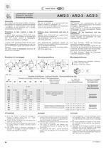
B6 CT17IGBD2.1 Posizioni di montaggio Mounting positions Montagepositionen M1 M2 M3 M4 M5 M6 Tab. 2.2 Generalità Si consiglia l'uso di oli a base sintetica. (Vedere a tale proposito le indicazioni riportate nel capitolo A, paragrafo 1.4.). Nella tabella 2.2 sono riportati i quantitativi di olio necessari per il corretto funzionamento dei riduttori. Prescrizioni in fase d’ordine e stato di fornitura i riduttori delle grandezze 25,35,40,50 sono forniti completi di olio sintetico di viscosità ISO 320. Per questi riduttori è necessario specificare la posizione di montaggio. I riduttori nelle grandezze...
Open the catalog to page 6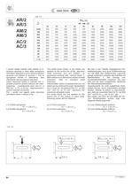
B8 CT17IGBD2.1 Tab. 2.5 The radial loads shown in the tables are applied on the centre line of the standard shaft extension and are related to gearboxes working with service factor 1. With reference to alternative values of shaft extension, refer to standard shaft extension. Intermediate values of speeds that are not listed can be obtained through interpolation but it must be considered that Fr1 at 500 min-1 and Fr2 at 15 min-1 represent the maximum allowable loads. For loads which are not applied on the centre line of the output or input shaft, following values will be obtained: at 0.3 from...
Open the catalog to page 8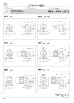
B32 CT17IGBD2.1 Dimensioni riduttori Dimensions gearboxes 1 Abmessungen Getriebes AM/1 - AR/1 - AC/1 1.8 Dimensioni 1.8 Dimensions 1.8 Abmessungen ACP (32) ACP (40 - 100) ARP (32) h H f b 15 a a1 a2 a3 i m m1 d1 5 d INT cRP LRP L1 L A S B h H f b a a3 i m m1 f1 d INT cRP LRP L1 L A S B d1 F R V M M M LM UM GM h H f b a a3 i m f1 d INT cCP L A S B F R V M M M LM UM GM h H f b S B 15 a a1 a2 a3 i m d INT cCP L A 5 h H f b S B 15 a a1 a2 a3 i 5 m d INT cMP L Y A AMP (32) AMP (40 - 100) h H f b a a3 i m f1 d INT cMP L A S B F Y R V M M M LM UM GM ARP (40 - 100) 2D 3D DownLoad 2D/3D Z4
Open the catalog to page 32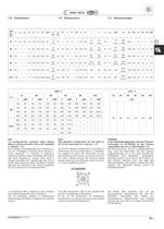
B33 1.8 Dimensioni 1.8 Dimensions 1.8 Abmessungen HINWEIS. In der Standardkonfiguration sind die 4 Flanschbohrungen im 45°-Winkel zu den Achsen angeordnet (wie ein x: siehe Kapitel 1.3). Bei B14-Flanschen, die mit (•) gekennzeichnet sind, sind die Bohrungen auf den Achsen angeordnet (wie ein +). Es sollte deshalb der Platzbedarf des Motorklem- menkastens beachtet werden, da er sich in 45°-Position zu den Achsen befinden wird. Die lage des Klemmenkastens des Motors wählen Sie bitte anhand der folgenden Skizze (Pos.5 ist Standardposition): N.B. La configurazione standard della flangia attacco motore...
Open the catalog to page 33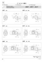
B34 CT17IGBD2.1 INT d G F m U cCF L V R V R INT d G F m U cCF L V R Y cMF L INT d G F m U AMF (32) ACF (32) ACF (40 - 100) INT m1 L1 d G F m U cRF LRF L V R d1 INT d G F m U L1 cRF LRP L m1 V R d1 ARF (32) ARF (40 - 100) AMF (40 - 100) INT d G F m U cMF L V R Y 1.8 Dimensioni 1.8 Dimensions 1.8 Abmessungen Dimensioni riduttori Dimensions gearboxes Abmessungen Getriebes AM/1 - AR/1 - AC/1 1 2D 3D DownLoad 2D/3D Z4
Open the catalog to page 34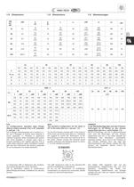
B35 32 40 50 60 80 100 F1 F2 F3 F1 F2 F3 F4 F1 F2 F3 F4 F1 F2 F3 F1 F2 F1 F2 F 120 140 160 120 140 160 200 120 140 160 200 160 200 250 250 300 250 300 G (g6) 80 95 110 80 95 110 130 80 95 110 130 110 130 180 180 230 180 230 R 100 115 130 100 115 130 165 100 115 130 165 130 165 215 215 265 215 265 V 9 9 10 9 9 10 13 9 9 10 13 10 13 15 15 15 15 15 U 3 3.5 3.5 3 3.5 3.5 3.5 3 3.5 3.5 3.5 3 3.5 3.5 4 4 4 4 AM AC AR cRF d h6 d1 j6 L L1 LRF m m1 INT 32 92 19 (14) 16 30 (40) 40 172 (162) M6 (M6) M6 33 40 141 19 (20) 16 40 (40) 40 221 (221) M6 (M6) M6 42 50 161 24 (25) 16 50 (50) 40 251 (251) M8 (M8)...
Open the catalog to page 35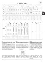
CT17IGBD2.1 B37 1.8 Dimensioni 1.8 Dimensions 1.8 Abmessungen IEC 25 35 41 45 25 35 41 45 Y cMP Y cMP Y cMP Y cMP cCP AMP../2 B5 120 116 — — 140 151.5 160 171.5 93.5 — — — 140 116 140 126.5 160 151.5 200 (IEC 80) 171.5 160 126.5 200 160 200 (IEC 90) 182.0 200 136.0 — — 250 184.0 B14 80 116 90 126.5 90 151.5 105 171.5 90 116 105 126.5 105 151.5 120 171.5 120 136.0 120 160 140 182.0 140 160 160 184.0 AMP../3 B5 120 116 120 144.0 140 168 160 188 140 116 140 144.0 160 168 200 188 — — — — B14 80 116 80 144.0 90 168 105 188 90 116 90 144.0 105 168 120 188 — — The cMP dimensions refer to the standard...
Open the catalog to page 37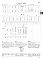
CT17IGBD2.1 B39 1.8 Dimensioni 1.8 Dimensions 1.8 Abmessungen AMF - ACF 25 35 41 45 F1 F2 F1 F2 F3 F1 F2 F3 F1 F2 F 105 120 140 160 200 140 160 200 160 200 FQ — — 110 120 150 110 120 150 120 160 G(g6) 70 80 95 110 130 95 110 130 110 130 R 85 100 115 130 165 115 130 165 130 165 V 7 7 9 9 13 9 9 13 9 13 U 3 3 3.5 3.5 3.5 3.5 3.5 3.5 3.5 3.5 NOTE: The standard configuration for the holes is 45° to the axles (like an x: see par. 1.3). For the B14 flanges marked with () the holes to fit the motor are on the axles (like a +). Therefore we suggest to check the dimensions of the terminal board of the...
Open the catalog to page 39All Stm Spa catalogs and technical brochures
 LONG PARALLEL SHAFT MOUNTED PL
46 Pages
 SKEW BEVEL HELICAL S
20 Pages
 BEVEL HELICAL O
76 Pages
 IN-LINE A
54 Pages
 SINGLE STAGE AR/1
54 Pages
Archived catalogs
 Industrial gearboxes
52 Pages
 Worm gearboxes
58 Pages
 Agriculture sector gearboxes
62 Pages
 Torque limiter
14 Pages
 Mechanical variators
12 Pages
 Right angle
34 Pages
 Electric motors & Inverters
81 Pages

- Electromotor
- Alternating current motor
- Asynchronous motor
- Planetary gearbox
- Three-phase motor
- Right angle gearhead
- Compact gearhead
- Gear train gear reducer
- Gearbox for industrial applications
- Transmission gearhead
- 380 V motor
- Single-stage gearhead
- Shaft gearhead
- Helical gear gearhead
- Machines gearbox
- 400 V motor
- 48 V motor
- Clamp gearbox
- Electric motor gearhead
- Bevel gearhead