- Catalogs
- stemmann-technik
- frost® ground contacts - Technical Details
- Products
- Catalogs
- News & Trends
- Exhibitions
frost® ground contacts - Technical Details
1 /16Pages

frost® ground contacts - Technical Details
1 /16Pages
Catalog excerpts

frost® Erdungskontakte Technische Details frost® Ground Contacts Technical Details STEMMANN-TECHNIK GMBH Fandstan Electric Group
Open the catalog to page 1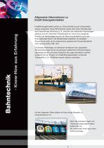
Allgemeine Informationen zu frost® Erdungskontakten frost®-Erdungskontakte werden zur Stromrückführung bei Schienenfahrzeugen eingesetzt. Diese Strombrücken stellen über einen Schleifkontakt eine niederohmige Verbindung z. B. zwischen dem stehenden Radsatzlagergehäuse und der rotierenden Radsatzwelle her. Durch eine geeignete Isolation der Radsatzlagerung wird der Strom ausschließlich durch den Erdungskontakt direkt in die Radsatzwelle eingeleitet, ein paralleler Strompfad ist außer durch entsprechend abgestimmte Schutzwiderstände nicht zulässig (siehe VDE 123). Da Radsatz-Rollenlager von elektrisch...
Open the catalog to page 2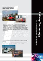
General Information on frost® Ground Contacts On the following pages we present some examples with regard to mounting situations. In case you will have special questions about Ground Contacts please do not hesitate to contact us. We are well prepared to forward our proposal. Railway Technology Due to the fact that wheel set roller bearings of electrically driven and extrernally supplied railway vehicles get damaged even with the flow of small electric current and necessitate a replacement of the bearings the application of frost® Ground Contacts is recommended. Threatening total breakdowns (i.e....
Open the catalog to page 3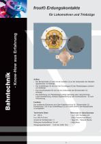
frost® Erdungskontakte Aufbau • Der Bürstenhalter (2) wird mit der Isolation (4) an der Außenseite des Radsatzlagerdeckels (1) befestigt. • Der Schleifkörper (5) wird auf der Druckkappe (8) des Radsatzlagers zentriert und befestigt. • Das Anschlusskabel (6) wird an der Außenseite des Bürstenhalter (2) befestigt. • Die Abdichtung zum Radsatzlager erfolgt wahlweise über Labyrinthringe, Labyrinthabdichtung, einfache Spaltabdichtung oder Kombinationen - je nach Anforderung. Funktion Der anfallende Rückstrom wird über Kabelanschluss (6), Bürstenhalter (2), Kohlebürsten (10) in den Schleifkörper (5)...
Open the catalog to page 4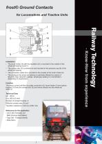
frost® Ground Contacts for Locomotives and Tractive Units 8 Installation • The brush holder (2) with the insulation (4) is mounted to the outside of the wheel set bearing cover(1). • The contact disc (5) is centred on and mounted to the pressure cap (8) of the wheel set bearing. • The connection cable (6) is mounted to the outside of the brush holder (2). • The sealing to the wheel set bearing is optionally effected by means of labyrinth rings, labyrinth sealings, simple gap sealing or a combination depending on requirement. Function The return current will flow via cable connection (6), brush...
Open the catalog to page 5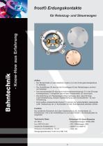
frost® Erdungskontakte Aufbau • Der Bürstenhalter (2) wird elektrisch isoliert (4) in dem Erdungskontaktgehäuse (1) befestigt. • Der Schleifkörper (5) wird auf der Druckkappe (8) des Radsatzlagers zentriert und befestigt. • Das Anschlusskabel (6) wird durch eine Kabelverschraubung (7) in das Erdungskontaktgehäuse (1) eingeführt und mit dem Bürstenhalter (2) verschraubt. • Die Abdichtung zum Radsatzlager erfolgt wahlweise über Labyrinthringe, Labyrinthabdichtung, einfache Spaltabdichtung oder Kombinationen - je nach Anforderung. • Durch Aufbau entsprechender Deckel (11) können hier unterschiedliche...
Open the catalog to page 6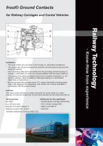
frost® Ground Contacts for Railway Carriages and Contol Vehicles 7 Installation • The brush holder (2) to be fixed in the housing (1), electrically insulated (4). • The contact disc (5) to be centred and screwed onto the pressure cap (8) of the wheel set bearing. • The connecting cable (6) to be inserted into the grounding contact housing (1) through a cable gland (7) and to be screwed together with the brush holder (2). • The sealing to the wheel set bearing may be by a number of solutions, i.e. via labyrinth washers, labyrinth sealing, simple gap sealing or a combination, depending on requirement....
Open the catalog to page 7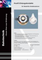
frost® Erdungskontakte Aufbau • Bei innengelagerten Radsätzen besteht die Möglichkeit, den Erdungskontakt direkt an das rotierende Rad anzubauen. • Das Erdungskontaktgehäuse (1) wird mit einer Drehmomentenstütze (12) drehgestellseitig gegen Rotation festgesetzt. • Diese Bauweise zeichnet sich durch die kompakten Abmaße aus. • Das Anschlusskabel wird am Kontaktarm (13) befestigt. Funktion Der Rückstrom wird über den isolierten Kontaktarm (13) mit Kohlebürste (10) beides nicht rotierend - in den rotierenden Schleifkörper (5) und Stirnflansch (14) und weiter in die Radsatzwelle(3) eingeleitet. Technische...
Open the catalog to page 8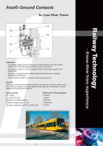
frost® Ground Contacts for Low Floor Trams Installation • A possibility exists to mount the ground contact directly onto the rotation wheel, when internally supported wheel sets are provided. • The ground contact (1) is fixed against rotation with torque support (12), bogie sides. • This type of design structure distinguishes itself because of compact dimensional tolerances. • The connection cable is mounted to the contact arm (13). Function The return current will flow via the insulated contact arm (13) with carbon brush (10) - both not rotating - into the rotating contact disc (5), front flange...
Open the catalog to page 9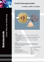
frost® Erdungskontakte für Metros, EMUs und DMUs Aufbau • Der Bürstenhalter (2) wird elektrisch isoliert (4) auf dem Radsatzlagerdeckel (1) befestigt. • Der Schleifkörper (5) ist auf der Druckkappe (8) des Radsatzlagers montiert. • Die Anbindung des Kabelanschlusses erfolgt an der Außenseite des Bürstenhalters (2). • Im Radsatzlager ist bereits die Abdichtung (15) zum Erdungskontakt vorhanden. Funktion Der Fahrzeug-Rückstrom wird über Kabelanschluss, Bürstenhalter (2), Kohlebürsten (10), in den Schleifkörper (5), die Druckkappe (8) und die Radsatzwelle (3) eingeleitet. Technische Daten Ieff:...
Open the catalog to page 10All Stemmann-technik catalogs and technical brochures
 Slip Ring Assemblies
12 Pages
 Stinger Systems - survey
4 Pages
 Conductor line systems - Survey
20 Pages
 Motor-driven cable reels
27 Pages


- Power supply unit
- DC power supply
- AC/DC power supply
- Electrical rotary joint
- Fixed reel
- Retractable reel
- Metal slip ring
- Cable reel
- Hollow-shaft electrical slip ring
- Motorized reel
- Mobile reel
- Capsule slip ring
- Guide rail
- Festoon system
- Aluminium slip ring
- Open reel
- Slide rail
- Truck-mounted reel
- Grounding device
- Solid-shaft slip ring