
- Catalogs
- Steel Smith
- SIDE CLAMPS


SIDE CLAMPS

SIDE CLAMPS
Overview
This document provides technical specifications and installation guidelines for the CP107 series side clamps, including part numbers CP107-16025, CP107-12023, CP107-08015, and CP107-10019.
Specifications
- Materials: Body made of quenched and tempered steel (S45C) with a black oxide finish.
- Clamping Force and Torque: Clamping forces range from 7,000 N to 30,000 N, with corresponding allowable screw torques between 8.5 N·m and 60 N·m depending on the model.
- Dimensions: Length (L) varies from 25 mm to 60 mm; other key dimensions include H, H1W, L1S, HP, D, S, W, X, Lf, P1, and M1, which are detailed per part number.
- Fasteners: Uses M8, M10, M12, or M16 hex socket head cap screws with one flat washer included per screw.
- Weight: Weight ranges from 115 g to 640 g depending on the clamp size.
Installation Instructions
To install the side clamps, drill holes for the cap screws and locking pins as specified in the dimensional drawings. The locking pin ensures secure positioning of the clamp during operation.
Key Parameters and Limitations
- Ensure the correct screw size and torque are applied to avoid damage or insufficient clamping force.
- Use the included flat washers to distribute load and prevent damage to the clamp body.
- Follow the specified hole dimensions and positions for proper installation and locking pin engagement.
Summary of Part Numbers and Key Dimensions
| Part Number | Length (L) mm | Clamping Force (N) | Allowable Torque (N·m) | Screw Size | Weight (g) |
|---|---|---|---|---|---|
| CP107-16025 | 60 | 30,000 | 60 | M16 | 640 |
| CP107-12023 | 50 | 20,000 | 50 | M12 | 390 |
| CP107-08015 | 40 | 8,500 | 25 | M8 | 225 |
| CP107-10019 | 32 | 7,000 | 15 | M10 | 115 |
Recommendations and Best Practices
- Use the specified torque values to ensure optimal clamping without over-tightening.
- Confirm the compatibility of screw sizes with the clamp model.
- Regularly inspect clamps and fasteners for wear or damage, especially in high-load applications.
Catalog excerpts

SIDE CLAMPS R©HS IflMO Part Number Drill a cap-screw hole and a locking-pin hole as specified on the left.
Open the catalog to page 1All Steel Smith catalogs and technical brochures
 CP720 flex locators
1 Page
 CP725
CP7251 Page
 BALL-LOCK CLAMPING PINS
4 Pages
 magnet-lock clamping pins
4 Pages
 Sliding locks for square bar
4 Pages
 QCWE KNOB-LOCKING CLAMPS
4 Pages
 Handles, knobs
73 Pages
 Hinges
21 Pages
 Swivel feet
55 Pages
 Compression latches
17 Pages
 CP104 TOE CLAMPS
1 Page
 TOE CLAMPS
1 Page
 HOOK CLAMPS
2 Pages
 HOOK-CLAMP ASSEMBLIES
2 Pages
 Steelsmith clamps 2017
2 Pages
 Automotive Clamps
1 Page
 787:clamping devices
1 Page
 6135-B:clamping devices
1 Page
 Swing Clamps
6 Pages
 Pneumatic Clamps
12 Pages
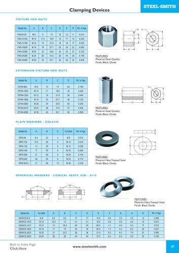 Clamping Devices
4 Pages
 Accessories
4 Pages
 Additional Locking Mechanism
6 Pages
 Automotive Clamps
16 Pages
 Squeeze Action Clamps
7 Pages
 Pull Action Clamps
7 Pages
 Straight Line Action
7 Pages
 Pull Back Clamps
2 Pages
 Horizontal Hold Down Action
6 Pages
 Cam Clamps
1 Page
 Leveling pads
1 Page
 Fixture elements
1 Page
 Shimpacks
2 Pages
 Straight line action
1 Page
 Spindles
2 Pages


