- Catalogs
- Stanford Research Systems
- SR865A — 4 MHz dual phase lock-in amplifier
SR865A — 4 MHz dual phase lock-in amplifier
1 /5Pages

SR865A — 4 MHz dual phase lock-in amplifier
1 /5Pages
Catalog excerpts

4 MHz Lock-In AmplifierSR865A — 4 MHz dual phase lock-in amplifier • 1 mHz to 4 MHz frequency range • Low-noise current and voltage inputs • Touchscreen data display - large numeric results, chart recordings, & FFT displays • 10 MHz timebase input and output • Dual reference mode • GPIB, RS-232, Ethernet and USB • HDMI video output • SR865A... $7950 (U.S. list) Superb performance. Outstanding value. They’re what you’ve come to expect from a Stanford Research Systems lock-in amplifier. And they’re delivered by the new SR865A 4 MHz Lock-in Amplifier, the latest in a line of innovative lock-ins from SRS. With unparalleled analog performance, sophisticated new digital signal processing features, a thoroughly modern, intuitive user interface, and a wide range of computer connectivity options, the SR865A is the ideal choice for any synchronous detection application. With over 30 years of lock-in design experience SRS has made every effort to optimize each detail of the SR865A. From a hefty toroidal transformer that eliminates switch-mode noise to iOS connectivity that brings the lock-in to your cell phone to advanced DSP filters that eliminate more noise while speeding up your experiment, the SR865A is truly the ultimate lock-in amplifier. Signal Inputs Lock-in performance starts at the front end. The SR865A front end offers both state-of-the art voltage and current input amplifiers. The voltage input is a switchable single-ended/ differential JFET-pair amplifier with 2.5 nV/^Hz of noise at 1 kHz and under 10 nV/vHz of noise at 10 Hz. The voltage input has a 10 MQ input impedance and can be AC or DC coupled. Input connector shields can be connected to the instrument ground through a user selectable 10 Q (Ground) or 10 kQ (Float) resistor. SRS Stanford Research Systems
Open the catalog to page 1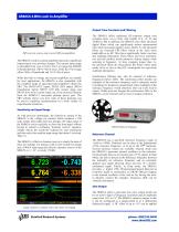
Output Time Constants and Filtering SRS current source and several SRS preamplifiers The SR865A’s built-in current amplifier represents a significant improvement over previous designs. The current input range is selectable from 1 μA or 10 nA. The 1 μA range has 400 kHz of bandwidth and 130 fA/√Hz of noise, while the 10 nA range offers 2 kHz of bandwidth and 13 fA/√Hz of noise. While the built in voltage and current amplifiers are suitable for most applications, the SR865A is also compatible with the complete range of specialized pre-amplifiers offered by SRS. The SR550 (FET input), SR552 (BJT...
Open the catalog to page 2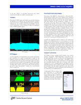
to the sine output. A rear-panel logic-level sync signal synchronized to the sine output is also provided. Timebase Rear-panel 10 MHz inputs and outputs are provided allowing the SR865A to be locked to an external frequency reference (such as the FS725 10 MHz Rubidium Frequency Standard). Alternatively, the 10 MHz output from the SR865A can be used to synchronize several lock-ins or other test equipment with a 10 MHz timebase input. FFT display FFT Displays Lock-in amplifiers are traditionally time-domain instruments but sometimes it’s easier to understand a signal in the frequency domain. The...
Open the catalog to page 3
Signal Channel Voltage inputs Sensitivity (output scale) Voltage input range Current input range Max input Input impedance Voltage input Current input Gain accuracy Noise (rms) Harmonic distortion CMRR Dynamic reserve Reference Channel Frequency range Timebase Input impedance Phase setting resolution Phase noise Int. ref Ext. ref (typ) Phase drift (typ) Single-ended or differential 1 nV to 1 V (voltage input) 1 fA to 1 pA (current input) 10 mV to 1 V (peak) 1 pA or 10 nA (peak) 1 V (peak) or 1 pA (peak) 10 MQ+25 pF, AC or DC coupled 1 kQ or 100 Q to virtual ground ±1 % (<200 kHz), ±2 % (to 4...
Open the catalog to page 4
CH1 output CH2 output X and Y outputs BlazeX Aux outputs Aux inputs Trigger input Signal monitor HDMI Timebase I/O Proportional to X or R (±10 V full scale thru 50 Q) Proportional to Y and 0 (±10 V full scale thru 50 Q) Proportional to X and Y (rear panel) (±10 V full scale thru 50 Q) Low latency ouput of X, ±2.0 V full scale or logic level reference sync output, either thru 50 Q 4 BNC D/A outputs, ±10.5 V thru 50 Q, 1 mV resolution 4 BNC A/D inputs, ±10.5 V, 1 mV resolution, 1MQ input TTL input triggers storage into the internal capture buffer Analog output of the signal amplifier Video output...
Open the catalog to page 5All Stanford Research Systems catalogs and technical brochures
 SR556
SR5561 Page
 QMSc
QMSc3 Pages
 FS730/1
4 Pages
 SC10
SC102 Pages
 PRS10
PRS104 Pages
 SR715/720
3 Pages
 CG635
CG6355 Pages
 PERF10
2 Pages
 SR865 DSP Lock-In Amplifier
5 Pages
 SR620
SR6204 Pages
 SIM900Mainframe
2 Pages
 SIM964Analog Limiter
1 Page
 SIM970Quad Digital Voltmeter
2 Pages
 SIM983Scaling Amplifier
1 Page
 SIM965Analog Filter
2 Pages
 SIM921AC Resistance Bridge
3 Pages
 SR250Gated Integrator
3 Pages
 SR540 Optical Chopper
1 Page
 SR640 Programmable Filters
3 Pages
 Rubidium Frequency Standard
4 Pages
 LCR Meters
3 Pages
 Synthesized Clock Generator
5 Pages
 UGAUniversal Gas Analyzer
3 Pages
 RGAResidual Gas Analyzers
5 Pages
 SR850DSP Lock-In Amplifier
4 Pages
 SR10/11/12Audio Switchers
2 Pages
 SR1Audio Analyzer
6 Pages
 6 GHz Vector Signal Generator
10 Pages
 SR255Fast Sampler
3 Pages
 SR245 Computer Interface
2 Pages
 SR200 Gate Scanner
1 Page
 SR630 Thermocouple Reader
3 Pages
 SR510/530 Lock-In Amplifiers
4 Pages
 IGC100 Ion Gauge Controller
4 Pages
 NL100 Nitrogen Laser
2 Pages
 SIM980 Summing Amplifier
1 Page
 SR235 Analog Processor
1 Page
 Laser Diode Controller
4 Pages
 DS335 Function Generator
2 Pages
 Audio Switchers
2 Pages


Archived catalogs
 Partial Pressure Monitor
2 Pages
 Analog PID Controller
2 Pages
 Optical Chopper
2 Pages
 Programmable Filters
3 Pages
 Distribution Amplifier
1 Page
 Audio Analyzer
6 Pages
 Residual Gas Analyzers
5 Pages
 Photon Counters
6 Pages
 Waveform Generator
2 Pages
 Lock in Amplifiers
3 Pages
 DSP Lock-in Amplifier
3 Pages


- Power supply unit
- DC power supply
- AC/DC power supply
- Measuring device
- Gas analyzer
- Concentration analyzer
- Monitoring analyzer
- Automatic analyser
- Benchtop analyser
- Digital temperature control
- Digital indicator
- Generator
- Temperature controller
- Tabletop power supply
- Compact power supply
- Real-time analyzer
- Integration analyzer
- Electronic filter
- Digital gauge