- Catalogs
- Stanford Research Systems
- DG645Digital Delay/Pulse Generator
DG645Digital Delay/Pulse Generator
1 /5Pages

DG645Digital Delay/Pulse Generator
1 /5Pages
Catalog excerpts

Digital Delay/Pulse Generator DG645 — Digital delay and pulse generator (4 or 8 channels) DG645 Digital Delay/Pulse Generator · 4 pulse, 8 delay outputs (opt.) · <25 ps rms jitter · Trigger rates to 10 MHz · Precision rate generator · Easy synchronization with 80 MHz mode locked lasers · Fast transition times · Ovenized crystal or Rb timebase (opt.) · Ethernet, GPIB and RS-232 interfaces The DG645 is a versatile digital delay/pulse generator that provides precisely defined pulses at repetition rates up to 10 MHz. The instrument offers several improvements over older designs — lower jitter, higher accuracy, faster trigger rates, and more outputs. The DG645 also has Ethernet, GPIB and RS-232 interfaces for computer or network control of the instrument. Delay Generator Timing All digital delay generators measure time intervals by counting cycles of a fast clock (typically 100 MHz). Most digital delay generators also have short programmable analog delays to achieve time intervals with finer resolution than the clock period. Unfortunately, one clock cycle of timing indeterminacy (typically 10 ns) can occur if the trigger is not in phase with the clock. The DG645 eliminates timing indeterminacy by measuring the timing of triggers with respect to the internal clock and compensating the analog delays. This approach reduces the jitter by about 100× and allows the internal rate generator to operate at any rate — not just a sub-multiple of the clock frequency. Triggering Stanford Research Systems The DG645 has many trigger modes. An internal rate generator, with less than 100 ps period jitter, may be set
Open the catalog to page 1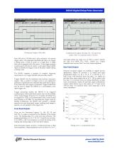
DG645 Digital Delay/Pulse Generator File Control Setup Measure Analyze Utilities Help 2:25 PM Combinatorial outputs showing 3 ns, 5 ns and 10 ns pulses with 1 ns transition times (5ns/div) and output offsets can range over ±2 VDC to source virtually any logic level (NIM, ECL, PECL, CMOS, etc.). Output transition times are less than 2 ns at any output amplitude. Rear-Panel Outputs Optional rear-panel outputs are available to support diverse applications. Option 01 provides a T0 output and eight logic levels, with transition times less than 1 ns. Option 02 provides these same outputs but as 30...
Open the catalog to page 2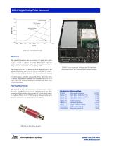
DG645 Digital Delay/Pulse Generator Ideal External Timebase Jitter vs. programmed delay Timebases The standard time base has an accuracy of 5 ppm, and a jitter of 10–8, which is suitable for many applications. Optional timebases are available for users who require better rate and delay accuracy or reduced rate and delay jitter. The timing error for a 1 s delay can be as large as 5 µs for the standard timebase, 200 ns for the OCXO timebase, but is only 500 ps for the rubidium timebase (all 1 year after calibration.) DG645 (cover removed) with optional Rb timebase. Rear panel shows the optional...
Open the catalog to page 3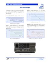
DG645 Digital Delay/Pulse Generator More About the Outputs A timing cycle is initiated by an internal or external trigger. The T0 output, whose leading edge is the zero-time reference, is asserted 85 ns after the trigger. The delay settings (A, B, C, D, E, F, G and H) determine the timing of the front-panel and rear-panel outputs. The front-panel outputs have adjustable amplitude, offset, and polarity (non-inverted or inverted). Opt. 02 rear-panel outputs (30 V) Front-panel outputs (adjustable) Option 01 rear-panel outputs provide T0 and eight delay outputs (A, B, C, D, E, F, G and H) to allow...
Open the catalog to page 4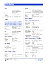
Channels 4 independent pulses controlled in position and width. 8 delay channels available as an option (see Output Options). Range 0 to 2000 s Resolution 5 ps Accuracy 1 ns + (timebase error × delay) Jitter (rms) Ext. trig. to any output 25 ps + (timebase jitter × delay) T0 to any output 15 ps + (timebase jitter × delay) Trigger delay 85 ns (ext. trig. to T0 output) Computer interfaces GPIB (IEEE-488.2), RS-232, and Ethernet. All instrument functions can be controlled through the interfaces. Non-volatile memory Nine sets of instrument configurations can be stored and recalled. Power <100 W,...
Open the catalog to page 5All Stanford Research Systems catalogs and technical brochures
 SR556
SR5561 Page
 QMSc
QMSc3 Pages
 FS730/1
4 Pages
 SC10
SC102 Pages
 PRS10
PRS104 Pages
 SR715/720
3 Pages
 CG635
CG6355 Pages
 PERF10
2 Pages
 SR865 DSP Lock-In Amplifier
5 Pages
 SR620
SR6204 Pages
 SIM900Mainframe
2 Pages
 SIM964Analog Limiter
1 Page
 SIM970Quad Digital Voltmeter
2 Pages
 SIM983Scaling Amplifier
1 Page
 SIM965Analog Filter
2 Pages
 SIM921AC Resistance Bridge
3 Pages
 SR250Gated Integrator
3 Pages
 SR540 Optical Chopper
1 Page
 SR640 Programmable Filters
3 Pages
 Rubidium Frequency Standard
4 Pages
 LCR Meters
3 Pages
 Synthesized Clock Generator
5 Pages
 UGAUniversal Gas Analyzer
3 Pages
 RGAResidual Gas Analyzers
5 Pages
 SR850DSP Lock-In Amplifier
4 Pages
 SR10/11/12Audio Switchers
2 Pages
 SR1Audio Analyzer
6 Pages
 6 GHz Vector Signal Generator
10 Pages
 SR255Fast Sampler
3 Pages
 SR245 Computer Interface
2 Pages
 SR200 Gate Scanner
1 Page
 SR630 Thermocouple Reader
3 Pages
 SR510/530 Lock-In Amplifiers
4 Pages
 IGC100 Ion Gauge Controller
4 Pages
 NL100 Nitrogen Laser
2 Pages
 SIM980 Summing Amplifier
1 Page
 SR235 Analog Processor
1 Page
 Laser Diode Controller
4 Pages
 DS335 Function Generator
2 Pages
 Audio Switchers
2 Pages


Archived catalogs
 Partial Pressure Monitor
2 Pages
 Analog PID Controller
2 Pages
 Optical Chopper
2 Pages
 Programmable Filters
3 Pages
 Distribution Amplifier
1 Page
 Audio Analyzer
6 Pages
 Residual Gas Analyzers
5 Pages
 Photon Counters
6 Pages
 Waveform Generator
2 Pages
 Lock in Amplifiers
3 Pages
 DSP Lock-in Amplifier
3 Pages


- Power supply unit
- DC power supply
- AC/DC power supply
- Measuring device
- Gas analyzer
- Concentration analyzer
- Monitoring analyzer
- Automatic analyser
- Benchtop analyser
- Digital temperature control
- Digital indicator
- Signal amplifying integrated circuit
- Temperature controller
- Tabletop power supply
- Compact power supply
- Real-time analyzer
- Integration analyzer
- Electronic filter
- Digital gauge