- Catalogs
- Stanford Research Systems
- DG535 Digital Delay/Pulse Generator
DG535 Digital Delay/Pulse Generator
1 /4Pages

DG535 Digital Delay/Pulse Generator
1 /4Pages
Catalog excerpts

Digital Delay/Pulse Generator DG535 — Digital delay and pulse generator (4-channel) DG535 Digital Delay/Pulse Generator · Four independent delay channels · Two fully-defined pulse channels · 5 ps delay resolution · <100 ps rms jitter · Adjustable amplitude and offset · Delays up to 1000 seconds · 1 MHz maximum trigger rate · Standard GPIB interface · Optional ±32 V outputs Stanford Research Systems The DG535 Digital Delay/Pulse Generator provides four precisely-timed logic transitions or two independent pulse outputs. The delay resolution on all channels is 5 ps, and the channel-to-channel jitter is typically 50 ps. Front-panel BNC outputs deliver TTL, ECL, NIM or variable level (–3 to +4 V) pulses into 50 Ω or high impedance loads. The high accuracy, low jitter, and wide delay range make the DG535 ideal for laser timing systems, automated testing, and precision pulse applications. Delay Outputs There are four delay output channels: A, B, C and D. The logic transitions of these outputs can be delayed from an internal or external trigger by up to 1000 seconds in 5 ps increments. The T0 pulse, which marks the beginning of a timing cycle, is generated by the trigger signal. The insertion delay between an external trigger and the T0 pulse is about 85 ns. Delays for each channel may be “linked” to T0 or any of the other delay channels. For instance, you can specify the delays of the four channels as:
Open the catalog to page 1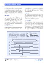
DG535 Digital Delay/Pulse Generator In this case, when the A delay is changed, the B output will move with it. This is useful, for instance, when A and B specify a pulse and you want the pulse width to remain constant as the delay of the pulse is changed. Regardless of how the delay is specified, each delay output will stay asserted until 800 ns after all delays have timed out. The delays will then become unasserted, and the unit will be ready to begin a new timing cycle. output is limited to 4 V. In addition, you can also separately select 50 Ω or high impedance termination for each output....
Open the catalog to page 2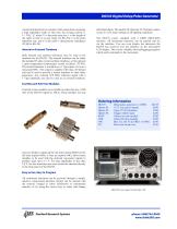
DG535 Digital Delay/Pulse Generator current limiting factor to consider when using them (assuming a high impedance load). In this case, the average current is: I = 2Vtf / Z, where V is the pulse step size, t is the length of the cable in time (5 ns per meter for RG-58), f is the pulse repetition rate, and Z is the cable’s characteristic impedance (50 Ω for RG-58). Internal or External Timebase Both internal and external references may be used as the timebase for the DG535. The internal timebase can be either the standard 25 ppm crystal oscillator timebase, or the optional 1 ppm temperature-compensated...
Open the catalog to page 3
Fast Rise Time (opt. SRD1) Channels Four independent delay outputs Range 0 to 999.999,999,999,995 seconds Resolution 5 ps Accuracy 1500 ps + timebase error × delay Timebase Standard: 25 ppm crystal oscillator Optional: 1 ppm TCXO (opt. 03) External: 10.0 MHz reference input RMS jitter <100 ps + (10–8 × delay) Trigger delay (typ.) 85 ns (ext. trigger to T0 output) Output amplitude +0.5 to 2.0 VDC Output offset –0.8 VDC (typ.) Transition time Rise (20/80 %) 100 ps (max.) Fall (20/80 %) 2000 ps (max.) Pulse aberrations Foot 4 % (typ.) Ring ±5 % (typ.) External Trigger Rate DC to 1/(1 µs + longest...
Open the catalog to page 4All Stanford Research Systems catalogs and technical brochures
 SR556
SR5561 Page
 QMSc
QMSc3 Pages
 FS730/1
4 Pages
 SC10
SC102 Pages
 PRS10
PRS104 Pages
 SR715/720
3 Pages
 CG635
CG6355 Pages
 PERF10
2 Pages
 SR865 DSP Lock-In Amplifier
5 Pages
 SR620
SR6204 Pages
 SIM900Mainframe
2 Pages
 SIM964Analog Limiter
1 Page
 SIM970Quad Digital Voltmeter
2 Pages
 SIM983Scaling Amplifier
1 Page
 SIM965Analog Filter
2 Pages
 SIM921AC Resistance Bridge
3 Pages
 SR250Gated Integrator
3 Pages
 SR540 Optical Chopper
1 Page
 SR640 Programmable Filters
3 Pages
 Rubidium Frequency Standard
4 Pages
 LCR Meters
3 Pages
 Synthesized Clock Generator
5 Pages
 UGAUniversal Gas Analyzer
3 Pages
 RGAResidual Gas Analyzers
5 Pages
 SR850DSP Lock-In Amplifier
4 Pages
 SR10/11/12Audio Switchers
2 Pages
 SR1Audio Analyzer
6 Pages
 6 GHz Vector Signal Generator
10 Pages
 SR255Fast Sampler
3 Pages
 SR245 Computer Interface
2 Pages
 SR200 Gate Scanner
1 Page
 SR630 Thermocouple Reader
3 Pages
 SR510/530 Lock-In Amplifiers
4 Pages
 IGC100 Ion Gauge Controller
4 Pages
 NL100 Nitrogen Laser
2 Pages
 SIM980 Summing Amplifier
1 Page
 SR235 Analog Processor
1 Page
 Laser Diode Controller
4 Pages
 DS335 Function Generator
2 Pages
 Audio Switchers
2 Pages


Archived catalogs
 Partial Pressure Monitor
2 Pages
 Analog PID Controller
2 Pages
 Optical Chopper
2 Pages
 Programmable Filters
3 Pages
 Distribution Amplifier
1 Page
 Audio Analyzer
6 Pages
 Residual Gas Analyzers
5 Pages
 Photon Counters
6 Pages
 Waveform Generator
2 Pages
 Lock in Amplifiers
3 Pages
 DSP Lock-in Amplifier
3 Pages


- Power supply unit
- DC power supply
- AC/DC power supply
- Measuring device
- Gas analyzer
- Concentration analyzer
- Monitoring analyzer
- Automatic analyser
- Benchtop analyser
- Digital temperature control
- Digital indicator
- Signal amplifying integrated circuit
- Temperature controller
- Tabletop power supply
- Compact power supply
- Real-time analyzer
- Integration analyzer
- Electronic filter
- Digital gauge