
- Catalogs
- StandexMeder Electronics GmbH
- Databook Reed Technology_EN

Databook Reed Technology_EN

Databook Reed Technology_EN
Catalog excerpts

LEADING BRANDS Reed Technology
Open the catalog to page 1
Content Reed Switch Characteristics Reed Switch Operational Characteristics . . . . . . . . . . . . . . . . . . . . . . . . . . . . . . . . . . . . . . . . . . . . . . . . . . . 7 The Basic Reed Switch . . . . . . . . . . . . . . . . . . . . . . . . . . . . . . . . . . . . . . . . . . . . . . . . . . . . . . . . . . . . . . . . 8 Basic Electrical Parameters of Reed Switch Products . . . . . . . . . . . . . . . . . . . . . . . . . . . . . . . . . . . . . . . . 10 How Reed Switches are used with a Permanent Magnet . . . . . . . . . . . . . . . . . . . . . . . . . . . . . . . . . . . . . 18 Reed...
Open the catalog to page 3
PRODUCT SOLUTIONS. AS DIVERSE AS THE MARKETS WE SERVE.
Open the catalog to page 4
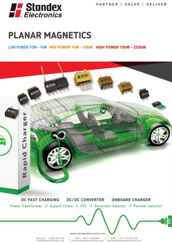
Standex Electronics is a worldwide market leader in the design, development and manufacture of standard and custom electro-magnetic components, including magnetics products and reed switch-based solutions. We offer engineered product solutions for a broad spectrum of product applications in all major markets, including but not limited to: Our magnetic offerings include planar, Rogowski, current, and low- and high-frequency transformers and inductors. Our reed switch-based solutions include KENT, MEDER and KOFU brand reed switches, as well as a complete portfolio of reed relays, and a comprehensive...
Open the catalog to page 5
CUSTOMER DRIVEN INNOVATION. PREMIER WORLDWIDE CAPABILITIES. COMMITMENT & EXPERTISE Standex Electronics has a commitment to absolute customer satisfaction and customer-driven innovation, with a global organization that offers premier sales support, engineering capabilities, and technical resources worldwide. Headquartered in Cincinnati, Ohio, USA, Standex Electronics has eight manufacturing facilities in six countries, located in the United States, Germany, China, Mexico, the United Kingdom, and Japan • Coil Molding & Packaging • Insert and Thermoset Molding • Low Pressure Molding (Hot Melt) •...
Open the catalog to page 6
• Stainless Steel Fabrication and Precise Laser Welding • Transformer Design And Manufacturing • Wave Soldering • Picoammeters • Destructive Pull Testers • Gauss / Teslameters ENGINEERING • Electronic sensor engineering • Circuit Design and PCB Layout • Patented Conductivity Sensors • Patented Inductive Sensors QUALITY/ LAB CAPABILITIES • Certifications: AS9100, ITAR, ISO9000, TS16949 • SPC Data Collection • Fully Equipped Certified Test Labs • 3-D Magnetic Sensor Mapping • Burn-in and Life Testing • Complete, In-House Machine Shop • Corona Discharge Testing Capabilities • Quick Turn Samples...
Open the catalog to page 7
Reed Switch Characteristics Reed Switch Operational Characteristics The Reed Switch was first invented by Bell Labs in the late 1930s. However, it was not until the 1940s when it began to find application widely as a sensor and a Reed Relay. Here it was used in an assortment of stepping/ switching applications, early electronic equipment and test equipment. In the late 1940s Western Electric began using Reed Relays in their central office telephone switching stations, where they are still used in some areas today. The Reed Switch greatly contributed to the development of telecommunications technology....
Open the catalog to page 9
Reed Switch Characteristics The Basic Reed Switch Fig. #1 The basic hermetically sealed Form 1A (normally open) Reed Switch and its component makeup. Fig. #2 The 1 Form C (single pole double throw) three leaded Reed Switch and its component makeup. A Reed Switch consists of two ferromagnetic blades (generally composed of iron and nickel) hermetically sealpowered in a glass capsule. The blades overlap internally in the glass capsule with a gap between them, and make contact with each other when in the presence of a suitable magnetic field. The contact area on both blades is plated or sputtered...
Open the catalog to page 10
Reed Switch Characteristics Figure 3 shows the general function of a Reed Switch with the us of a permanent magnet. Fig. #3 The basic operation of a Reed Switch under the influence of the magnetic field of a permanent magnet. The polarization of the reed blades occurs in such a manner to offer an attractive force at the reed contacts. The use of a coil wound with copper insulated wire. See Figure 4. Fig. #4 A Reed Switch sitting in a solenoid where the magnetic field is strongest in its center. Here the reed blades become polarized and an attractive force exists across the contacts. When a permanent...
Open the catalog to page 11
Reed Switch Characteristics Basic Electrical Parameters of Reed Switch Products Pull-In (PI) is described as that point where the contacts close. Using a magnet, it is usually measured as a distance from the Reed Switch to the magnet in mm (inches) or in field strength AT, mTesla, or Gauss. In a coil, the Pull-In is measured in volts across the coil, mA flowing in the coil, or ampere-turns (AT). Generally, this parameter is specified as a maximum. No matter how well the reed blades are annealed, they will still have a slight amount of retentivity (a slight amount of magnetism left in the blades...
Open the catalog to page 12
Reed Switch Characteristics Drop-Out (DO) is described as that point where the contacts open and has similar characteristics as the Pull-In above. It is also described as release or reset voltage current or AT. Hysteresis exists between the Pull-In and Drop-Out and is usually described in the ratio DO/PI expressed in %. The hysteresis can vary depending upon the Reed Switch design, (Figure #7), where variations in plating or sputtering thickness, blade stiffness, blade overlap, blade length, gap size, seal length, etc. will all influence this parameter. See Figure 7 for example of hysteresis...
Open the catalog to page 13
Reed Switch Characteristics Fig. #9 A schematic diagram of a typical circuit used for measuring the dynamic contact resistance across the contacts of a Reed Switch. Fig. #10 A typical dynamic contact resistance portrayal showing the first closure, bouncing, dynamic noise and pattern generated by waver-ing contacts Applying the frequency described above to a coil, the contacts will operate and close in approximately ½ mA. The contacts may then bounce for about 100ms and undergo a period of dynamic noise for as much as ½ ms. This dynamic noise is generated by the contacts continuing to bounce but...
Open the catalog to page 14All StandexMeder Electronics GmbH catalogs and technical brochures
 Magnetic Floats
2 Pages
 Activate Distance
40 Pages
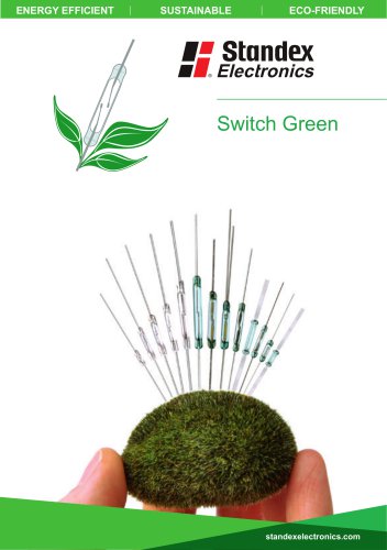 Switch Green
6 Pages
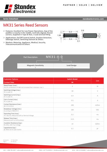 MK31 SERIES REED SENSOR
2 Pages
 Product Line Brochure Magnetics
24 Pages
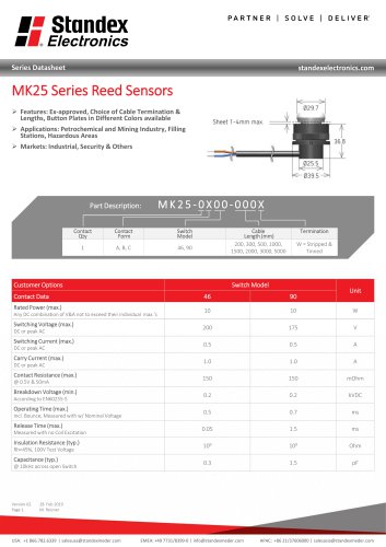 MK25 SERIES REED SENSOR
3 Pages
 MK28 SERIES REED SENSOR
2 Pages
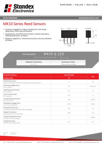 MK10 SERIES REED SENSOR
2 Pages
 MK02-6 SERIES REED SENSOR
2 Pages
 MK06 SERIES REED SENSOR
3 Pages
 MK27 SERIES REED SENSOR
3 Pages
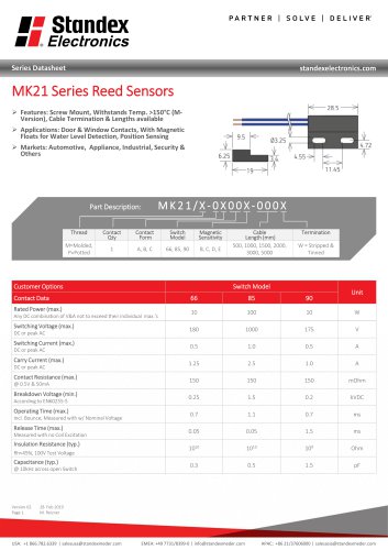 MK21 SERIES REED SENSOR
3 Pages
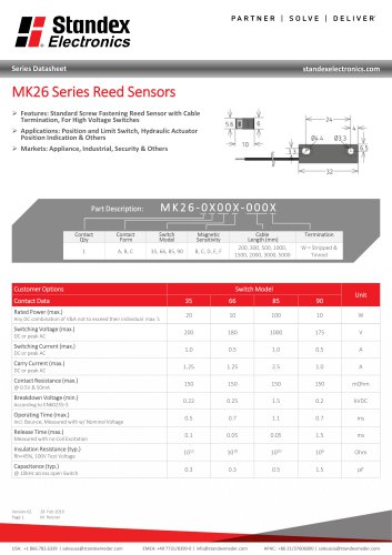 MK26 SERIES REED SENSOR
3 Pages
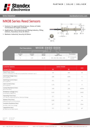 MK08 SERIES REED SENSOR
3 Pages
 MK02 SERIES REED SENSOR
3 Pages
 MK13 SERIES REED SENSOR
3 Pages
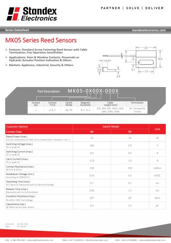 MK05 SERIES REED SENSOR
3 Pages
 MK04 SERIES REED SENSOR
3 Pages
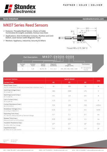 MK07 SERIES REED SENSOR
3 Pages
 MK03 SERIES REED SENSOR
2 Pages
 MK14 SERIES REED SENSOR
3 Pages
 MK18 SERIES REED SENSOR
2 Pages
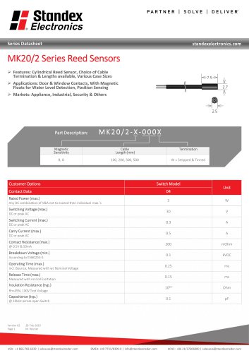 MK20/2 SERIES REED SENSOR
2 Pages
 MK01 SERIES REED SENSOR
3 Pages
 MK30 SERIES REED SENSOR
2 Pages
 MK15 SERIES REED SENSOR
2 Pages
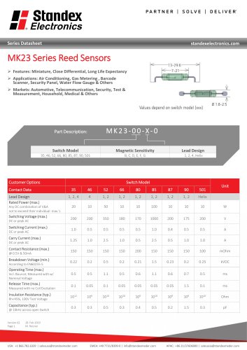 MK23 SERIES REED SENSOR
4 Pages
 MK22 SERIES REED SENSOR
2 Pages
 MK17 SERIES REED SENSOR
2 Pages
 MK16 SERIES REED SENSOR
2 Pages
 MK24 SERIES REED SENSOR
2 Pages
 LS05 Series Data Sheet
2 Pages
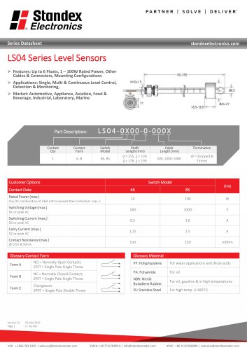 LS04 Series Data Sheet
2 Pages
 LS03 Series Data Sheet
3 Pages
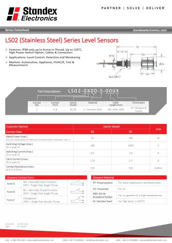 LS02-S Series Data Sheet
2 Pages
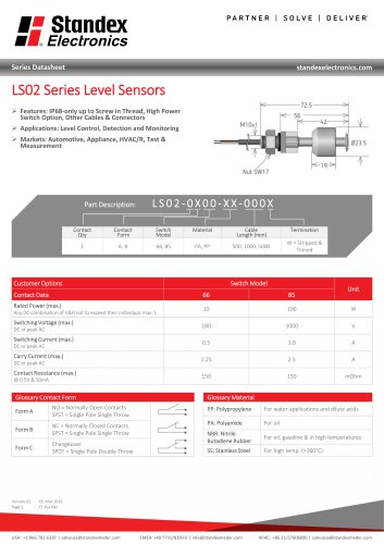 LS02 Series Data Sheet
2 Pages
 LS01 Series Data Sheet
2 Pages
 PQ32 Planar Inductors
1 Page
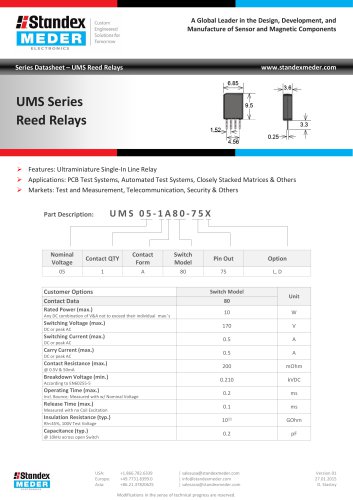 UMS SERIES REED RELAY
3 Pages
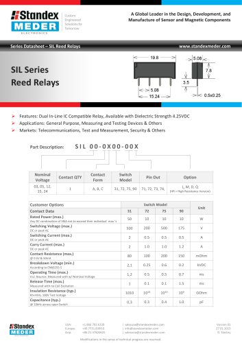 SIL SERIES REED RELAY
3 Pages
 SIL RF SERIES REED RELAY
3 Pages
 SIL HV SERIES REED RELAY
3 Pages
 RM05-8A-S SERIES REED RELAY
3 Pages
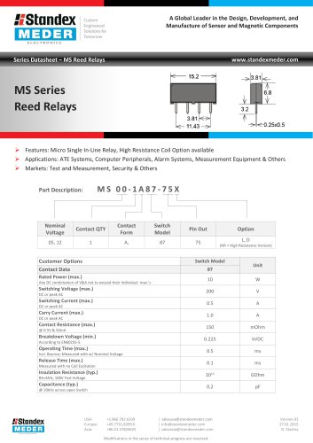 MS SERIES REED RELAY
3 Pages
 MRX SERIES REED RELAY
3 Pages
 LI SERIES REED RELAY
3 Pages
 KT SERIES REED RELAY
3 Pages
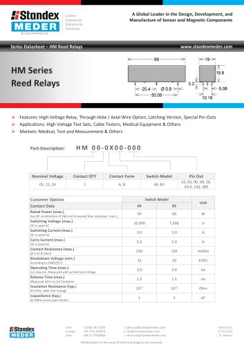 HM SERIES REED RELAY
3 Pages
 HI SERIES REED RELAY
3 Pages
 HF SERIES REED RELAY
3 Pages
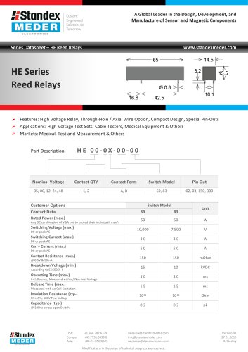 HE SERIES REED RELAY
3 Pages
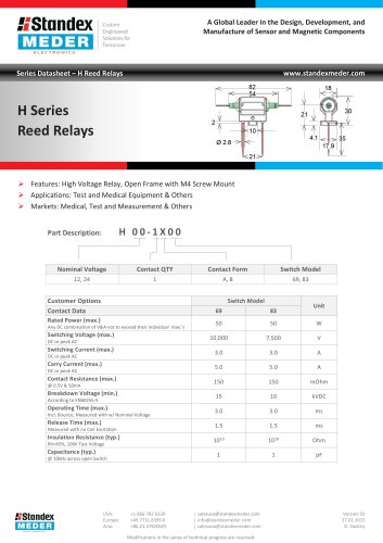 H SERIES REED RELAY
2 Pages
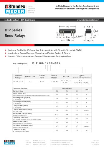 DIP SERIES REED RELAY
3 Pages
 DIL SERIES REED RELAY
3 Pages
 CRR SERIES REED RELAY
3 Pages
 CRF SERIES REED RELAY
3 Pages
 BT SERIES REED RELAY
3 Pages
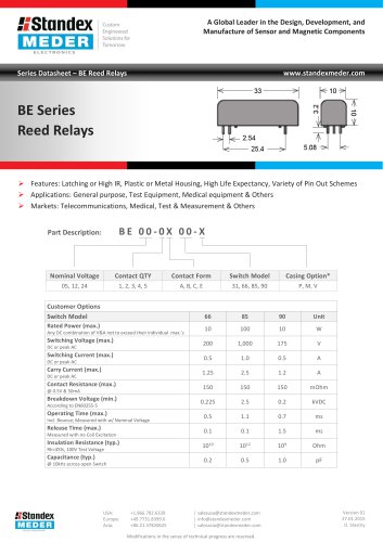 BE SERIES REED RELAY
3 Pages
 Optocoupler 567 Series
2 Pages
 Optocoupler 535 Series
2 Pages
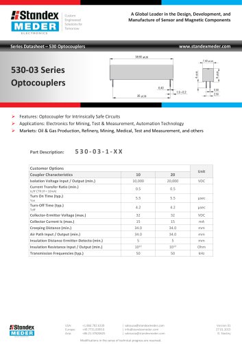 Optocoupler 530-03 Series
2 Pages
 Optocoupler 530-70 Series
2 Pages
 Optocoupler 528 Series
2 Pages
 Optocoupler 525 Series
2 Pages
 Optocoupler 522 Series
2 Pages
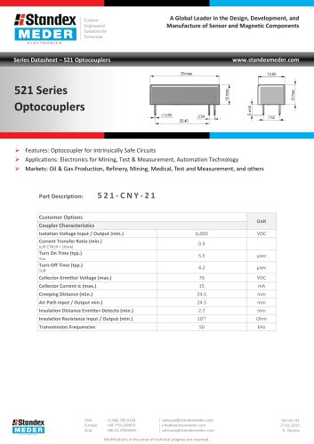 Optocoupler 521 Series
2 Pages
















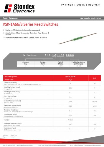


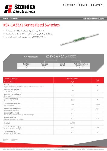

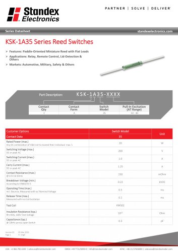


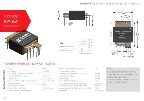




- Standex proximity sensor
- Standex level switch
- Single-pole switch
- Standex liquid level switch
- Standex switching relay
- Cylindrical proximity sensor
- Technology switch
- Inductive proximity sensor
- IP67 proximity sensor
- Standex float level switch
- Encapsulated transformer
- Standex power transformer
- Standex single-phase transformer
- Stainless steel level detector
- Standex isolation transformer
- Low-voltage transformer
- Standex threaded level switch
- Three-phase transformer
- Tank level limit switch