
Catalog excerpts

DETECTORS Dry Electrolytic Conductivity Detector - DELCD The Dry Electrolytic Conductivity detector, or DELCD, is selective to chlorinated and brominated molecules. It differs from the traditional wet ELCD in that it does not use a solvent electrolyte, and the reaction products are detected in the gaseous phase. The SRI DELCD is available alone or in combination with the FID detector. On its own, the detection limits of the DELCD are in the low ppb range. In combination with the FID, its detection limits are in the low ppm range. The FID/DELCD combination enables the operator to reliably identify hydrocarbon peaks detected by the FID as halogenated or not. Because the DELCD operates at 1000oC, it can tolerate the water-saturated FID effluent, measuring the chlorine and bromine content simultaneously with the FID measurement of the hydrocarbon content. All hydrocarbons are converted by the FID flame to CO2 and H2O prior to reaching the DELCD, thus preventing contamination of the DELCD by large hydrocarbon peaks. DELCD reaction chamber insulation DELCD DELCD collector heater & thermocouple terminal leads Hydrogen supply DELCD collector & thermocouple terminal and gain switch FID collector terminal and gain switch DELCD collector & thermocouple leads
Open the catalog to page 1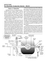
DETECTORS Dry Electrolytic Conductivity Detector - DELCD Theory of Operation The DELCD consists of a small ceramic tube— the DELCD reactor—heated to 1000oC. Inside the reactor, a platinum thermocouple measures the detector temperature, and a nichrome collector electrode measures the conductivity of the gases flowing through the DELCD. The detector response is dependent upon its temperature. Therefore, the control circuit must maintain the temperature, within a fraction of a degree, at 1000oC. When combined with the FID detector, the DELCD is mounted on the FID exhaust. Column effluent...
Open the catalog to page 2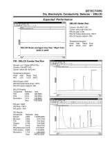
DETECTORS Dry Electrolytic Conductivity Detector - DELCD DELCD Noise Run Column: 15m MXT-VOL Carrier: helium @ 10mL/min DELCD gain: LOW DELCD heater block temp: 150oC DELCD reactor setpoint: 260 Temperature program: Initial Hold Ramp Final 80oC 20.00 0.00 80oC FID / DELCD Combo Test Run Sample: 1 ^L 100ppm BTEX Plus Column: 15m MXT-VOL Carrier: helium @ 10mL/min Temperature program: Initial Hold Ramp Final DELCD gain: LOW DELCD heater block temp: 150oC DELCD reactor setpoint: 260 DELCD Results: Component TCE PCE Bromoform FID gain: HIGH FID temp: 150oC FID ignitor: -400 Ethyl...
Open the catalog to page 3
DETECTORS Dry Electrolytic Conductivity Detector - DELCD General Operating Procedure The FID/DELCD combination detector can be operated in the Combo Mode, the High Sensitivity Mode (DELCD only), or the FID only mode. Combo Mode In the Combo Mode, the DELCD is operated after the FID; the FID signal is usually connected to Channel 1 on the PeakSimple data system, while the DELCD signal is on channel 2 or 3. Each detector amplifier is factory labeled with the data channel to which it is connected. The DELCD response in this mode is useable from 1 to 1000 nanograms with a slightly quadratic...
Open the catalog to page 4
DETECTORS Dry Electrolytic Conductivity Detector - DELCD General Operating Procedure continued FID/DELCD - FID Only 1. Remove the DELCD heater wires from the push terminals. Remove the three DELCD collector and thermocouple wires (yellow, white and red) from the scew terminals. 2. Disconnect the DELCD detector assembly from the FID exhaust by using a wrench to loosen the 1/4” Swagelok fitting securing the two detector parts together. 3. Use a cap nut to seal the DELCD connection on the FID flameport. 4. Set the FID amplifier gain switch to HIGH for most hydrocarbon applications. If peaks of...
Open the catalog to page 5
DETECTORS Dry Electrolytic Conductivity Detector - DELCD Installing the Spare DELCD Cell Each SRI DELCD detector is shipped with a spare DELCD cell. Because the DELCD heater operates close to 1000oC, it will burn out and fail eventually. Follow the instructions below to remove the old cell and install the new one. 1. With the GC power OFF, remove the DELCD heater wires (2) from the push terminals and the DELCD thermocouple and collector wires (3) from the screw terminals. 2. Remove the DELCD cell by using a wrench to loosen the 1/4” fitting that secures it on the FID exhaust port or on the...
Open the catalog to page 6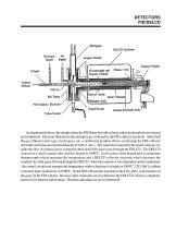
Graphic Ferrule DELCD TpsmaJUoc DETECTORS FID/DELCD GimjitiiTe Ferrule Tluifinocwj^ ud EtJujuisI Y»l DWKtH GaUtodc v OdlBilW Al'.cj? FUrncpan Body Vesptl Ferrate OMMlic ELecdfiGt Prune- Ti-riim FOffUlc As diagrammed above, the sample enters the FID flame from the column where hydrocarbons are ionized and combusted. Electrons liberated in the ionization are collected by the FID collector electrode. About half the gas effluent (carrier gas + hydrogen + air + combustion products) flows out through the FID collector electrode which has an internal diameter of .040 (1 mm.). The restriction...
Open the catalog to page 7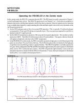
DETECTORS FID/DELCD Operating the FID/DELCD in the Combo mode In the combo mode, the DELCD is operated after the FID. The FID signal is usually connected to Channel 1 on the PeakSimple data system. The DELCD signal may be on Channel 2 or 3. Each detector amplifier is labeled at the factory with the data channel to which it has been connected. Detector signals may be connected to any available data channel by simply attaching the white and black signal wires to the screw terminals on the A/D board inside the GC. 1) Set the FID hydrogen and air flows for normal FID operation. This is...
Open the catalog to page 8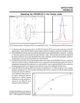
DETECTORS FID/DELCD Operating the FID/DELCD in the Combo mode DELCD peak overlaid on FID peak for PCE, then expanded for clarity. The smaller peak is the DELCD response. 1) As shown in the chromatogram above, the DELCD peak for PCE occurs at the same time as the FID peak for PCE. Notice that the DELCD peak exhibits a little bit of tailing compared to the FID response. 2) In the FID/DELCD combo mode, the minimum detectable amount is approximately 1 nanogram. Assuming a 1 microliter injection, this translates into approximately 1 ppm. The exact detection limit will depend on the analyte...
Open the catalog to page 9All SRI Instruments catalogs and technical brochures
-
Mud-logger GC
6 Pages
-
5030 Autosampler Retrofit
1 Pages
-
8640 Integrated Autosampler
4 Pages
-
NPD to FID Detector Conversion
12 Pages


