
Catalog excerpts
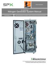
INSTRUCTION MANUAL Nitrogen Generator System Manual N2-GEN-MANUAL 3.7 READ AND UNDERSTAND THIS MANUAL PRIOR TO OPERATING OR SERVICING THIS PRODUCT. Patented 2nd Generation Nitrogen Generator Systems are manufactured and distributed by Waukesha® Service & Components, a division of SPX Transformer Solutions, Inc. U.S. Patent Nos. 6,581,694; 6,568,287; 6,062,821; 5,902,381 and 5,744,764.
Open the catalog to page 1
2nd GENERATION NITROGEN GENERATOR SYSTEM MANUAL General Description & Principle of Operation Page 2 Nitrogen Membrane Principle of Operation Page 3 Safety Information Page 4 Single Transformer Installation Page 6 Multiple Transformer Installation Pages 7-8 Electrical Connections Page 9 General Component Identification Pages 10-11 Start-up I nstructions Pages 12-14 Climate Control Description & Operation Pages 15-17 System Alarms Page 18 System Shut Down Procedure Page 19 Periodic Maintenance Pages 20-21 Compressor Conservator Circuit Page 23 Patented 2nd Generation Nitrogen Generator...
Open the catalog to page 2
2nd GENERATION NITROGEN GENERATOR SYSTEM MANUAL GENERAL DESCRIPTION The N2 Nitrogen Generator is designed for use on tap changers, breakers, main tanks or any other electrical device requiring a gas-blanketed enclosure. The unit produces nitrogen by separating oxygen from compressed air by means of hollow fiberglass separation membranes. The compressed air is supplied by an on-board compressor and the generated nitrogen (N2) is fed to internal storage vessels. The output concentration of the air separator (nitrogen purity) is factory pre-set. The final regulator system maintains the...
Open the catalog to page 3
2nd GENERATION NITROGEN GENERATOR SYSTEM MANUAL NITROGEN MEMBRANE PRINCIPLE OF OPERATION Refer to Figure 2 below. Compressed air flows into the hollow fiber membrane. Various air components, such as oxygen, nitrogen, carbon dioxide and water vapor pass through the membrane wall, but the rate at which this occurs differs for the various gases. Oxygen and water vapor have a high diffusion rate and diffuse rapidly through the membrane wall. Nitrogen has a low diffusion rate and penetrates the membrane wall slowly, mainly at the end of the hollow fibers. The purity of the nitrogen at the end of...
Open the catalog to page 4
2nd GENERATION NITROGEN GENERATOR SYSTEM MANUAL SAFETY INFORMATION Proper use of this equipment is important for your personal safety and for trouble-free functioning of the unit. Incorrect control or attempts to perform adjustments could cause damage or lead to incorrect gas supply. Be sure to read and understand all instructions before attempting to operate the unit. The unit is designed to produce nitrogen. The nitrogen is supplied by an internal generator that produces nitrogen from ambient air through a process of separating oxygen from normal air. You must not use the unit for any...
Open the catalog to page 5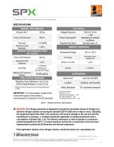
2nd GENERATION NITROGEN GENERATOR SYSTEM MANUAL SPECIFICATIONS NOMINAL PERFORMANCE Power Consumption* Flow rate* Dew Point of N2 Delivered* Potential Free Alarm AVERAGE PERFORMANCE FROM –40° TO 50°C 120V AC, 60 Hz 1–19A depending on ambient conditions Normally open,1A AMBIENT CONDITIONS Temperature Range Normally clean ambient air Relative Humidity Flow Rate 1.0 SLPM Continuous 5.0 SLPM Purge Maximum Oil Volume to Blanket FINAL OUTPUT PRESSURE Regulator Output Between 0 and 2.0 psi Control Range Between 0.2 and 5.5 psi Noise Level Outdoors, wall mounted * Nitrogen Delivery properties at...
Open the catalog to page 6
2nd GENERATION NITROGEN GENERATOR SYSTEM MANUAL INSTALLATION – SINGLE TRANSFORMER CAUTION: The unit must be mounted in an upright position. Do not mount unit on its side or back. The unit MUST be vertical for 12 hours before turning the unit on. WARNING: A crane, or similar lifting device, is required to lift and secure unit to wall mounting surface. CAUTION: Do not block the ventilation inlets and outlets as this could cause overheating and damage to the unit. WARNING: Support structure and mounting hardware must be capable of supporting the generator weight of 380 lbs. minimum. Cabinet is...
Open the catalog to page 7
2nd GENERATION NITROGEN GENERATOR SYSTEM MANUAL INSTALLATION - MULTIPLE TRANSFORMERS A CAUTION: The unit must be mounted in an upright position. Do not mount unit on its side or back. The unit MUST be vertical for 12 hours before turning the unit on. A WARNING: A crane or similar lifting device is required to lift and secure unit to wall mounting surface. A CAUTION: Do not block the ventilation inlets and outlets as this could cause overheating A WARNING: Support structure and mounting hardware must be capable of supporting the generator weight of 380 lbs. minimum. Cabinet is designed to be...
Open the catalog to page 8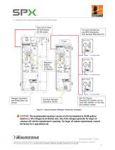
2nd GENERATION NITROGEN GENERATOR SYSTEM MANUAL Use one or more N2 Generators for N2 supply For each transformer, use SPX Waukesha Part Number MN2-0A0133 7.5 psi Regulator Bypass Valve set to “Bypass” TO TRANSFORMER THE FAN OR HEATER IS NOT OPERATING Confirm that the voltage input to the PTC2 assembly is the correct voltage. Check heater assembly terminals at the power harness quick-connect plug. Check wiring harness for cuts or bare insulation. Confirm fan assembly has not been clogged with debris—clean if necessary. Nitrogen Generator with Bottle Back-Up Shown Mini N2 Shown. Standard N2...
Open the catalog to page 9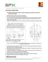
2ND GENERATION NITROGEN GENERATOR SYSTEM MANUAL ELECTRICAL CONNECTIONS A WARNING: Electrical shock hazard. Failure to follow these instructions could result in serious injury or death. ■ Electrical ground is required on this piece of equipment. Do not use an extension cord with this piece of equipment. ■ The unit should be grounded according to local electrical codes to prevent the possibility of electrical shock. It requires a grounded receptacle with separate electrical lines, protected by fuses or circuit breaker of the proper rating. ■ Check with a qualified electrician if you are in...
Open the catalog to page 10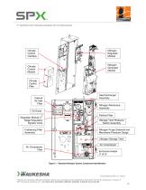
2nd GENERATION NITROGEN GENERATOR SYSTEM MANUAL Climate Control Interface Nitrogen Regulator Module Nitrogen Generator Module Climate Control Module Climate Control Filter Heat Exchanger Assembly Cabinet Air Inlet Filter Nitrogen Membrane Assembly Particle Filter Regulator Module 3 Stage Regulation Bypass Valve Storage Tank Pressure Switch Assembly Coalescing Filter Assembly Nitrogen Purge Solenoid and Membrane Pressure Gauge Nitrogen Storage Tank Air Compressor Figure 7 – Standard Nitrogen System Component Identification Patented 2nd Generation Nitrogen Generator Systems are manufactured...
Open the catalog to page 11All SPX Transformer Solutions catalogs and technical brochures
-
PTC2
2 Pages
-
Large Power Transformers
6 Pages
-
Mini Inert Air Systems
2 Pages
-
Waukesha® UZDvac
2 Pages
-
Waukesha® UZD® Brochure
2 Pages


