Hytec
1 /140Pages

Hytec
1 /140Pages
Catalog excerpts
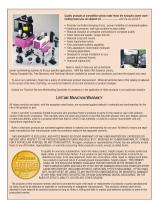
Precisely controlled clamping forces...proven reliability of component systems Continuous pressure, stall-type systems increase safety Reduced vibration of workpiece and tooling for increased quality Faster feeds and speeds...longer tool life Reduced scrap and rework Faster load/unload cycles Fully automated systems capability Fully adaptable to multi-station hydraulic clamping applications • Designed for simple installation in your present or planned fixtures • Improved ergonomics Hytec is ready to help you set up hydraulic power workholding systems to fit your specific applications. With the...
Open the catalog to page 2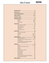
Alphabetical Index Numerical Index Workh oldin g Devices
Open the catalog to page 3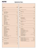
Alphabetical Index DESCRIPTION
Open the catalog to page 4
Numerical Index CATALOG NO.
Open the catalog to page 5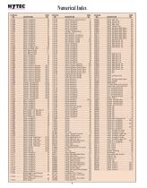
Numerical Index CATALOG NO.
Open the catalog to page 6
Power Workholding Systems Ap plication A Among the simplest systems, single-acting spring return actuators can be operated with a single pressure line from this 58219 air/ hydraulic pump or any Hytec constant pressure pump with a 9504 pump-mounted valve. Ap plication B Multiple double-acting actuators can be operated simultaneously, powered by a pump with a 9504 pump-mounted manual control valve. Ap plication C Two pairs of single-acting actuators are independently operated by 9503 remote mounted control valves and powered by one pump. Check valves prevent return line pressure fluctuations from...
Open the catalog to page 7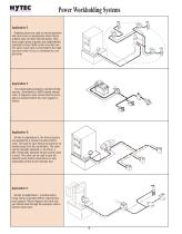
Power Workholding Systems Application E Rotating unions are used to connect pressure and return lines on applications where fixture rotation does not allow fixed plumbing. Here, three single-acting actuators are independently operated by three, 9503 remote mounted control valves. Each valve is connected to the rotating union which in turn, is connected to a single pump. Application F Two single-acting actuators operate simultaneously, controlled by a 9503 remote manual valve. A sequence valve insures that the workpiece is clamped before the work support is locked. Application G Similar to Application...
Open the catalog to page 8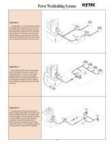
Power Workholding Systems Application I Like application C, two single-acting systems are independently operated by remote mounted control valves. Here the pressure reducing valve allows each system to have its own maximum pressure. The cylinder on the left operates at the pressure of the power source and the one on the right can be set at a lower pressure by adjusting the pressure reducing valve. Application J Hytec’s Manual Pallet Valve is the simplest way to disconnect the power source from a pressurized pallet. For use only with singleacting actuators, it provides an automatic, leak free...
Open the catalog to page 9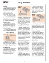
Design Information PLANNING The most important and cost effective part of the fixture design process is planning. All facets of the project should be considered, and questions answered before fixture designing begins. • How many operations are required? • What machine will be used? • What is the expected cycle time? • How many parts will be run? How often? • How fast must the workpiece be changed? The answers to questions like these will help determine the relative cost/benefit of the clamping system chosen for the fixture. The following information will help prove that a hydraulic power clamping...
Open the catalog to page 10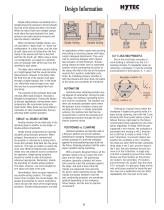
Design Information Single acting clamps can develop only a limited amount of pressure to force hydraulic fluid out of the clamp and allow it to retract. When the return fluid from multiple clamps must share the same hydraulic line, back pressure can easily become excessive and slow the clamp’s retraction. When connecting multiple clamps, you can use either a “daisy chain” or “home run” configuration. In a daisy chain, you use a tee at each clamp and run tubing from the first clamp to the second and then to the third and then the fourth, etc. When using a home run configuration, you begin at a...
Open the catalog to page 11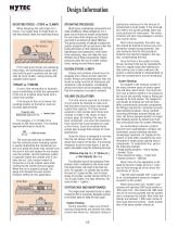
Design Information RESISTING FORCES – STOPS vs. CLAMPS OPERATING PRESSURES When designing the solid stops for a fixture, it is usually best to locate them so that they directly resist the machining forces. Most Hytec workholding components are rated at 5000 psi. When designing, it is a good rule of thumb to choose components for your fixture that will give you the forces you need at a pressure of about 3000 psi. This gives you plenty of latitude to adjust the system pressure both up and down when fine tuning the fixture on the machine tool. Operating at lower pressures, while sometimes necessary,...
Open the catalog to page 12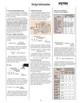
Design Information CALCULATING MACHINING FORCES To help you choose the right cylinders, clamps, and work supports, it is important to know how much clamping or supporting force is necessary. There are numerous ways to calculate the approximate forces that the cutting tool places on the workpiece. P l e a s e n o t e t h a t the results of these calculations are esti mates and must never replace experience, common sense, and caution. In addition, these results indicate only the magnitude of the force, not the direction. Depending on the specific application, the direction of the force may vary...
Open the catalog to page 13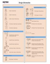
Design Information C YLINDER SYMBOLS Cylinder, Single-Acting Work Support, Spring Advance Cylinder, Double-Acting Work Support, Air Advance Cylinder, Single or Double-Acting Electric/Hydraulic Pump Pull Cylinder, Single-Acting, Spring Return Air/Hydraulic Pump, Reciprocating Pull Cylinder, Single-Acting Air/Hydraulic Pump, Reciprocating 2-stage C LAMP SYMBOLS Intensifier Swing/Pull Clamp, Single-Acting w/Flow Restrictor Valve C ONTROL V ALVE SYMBOLS Swing/Pull Clamp, Double-Acting Directional Control Valve, Manual 4-Way, 2-Position w/Inlet Check Valve Swing/Pull Clamp, Single-Acting Directional...
Open the catalog to page 14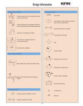
Design Information C ONTROL V ALVE SYMBOLS A CCESSORY SYMBOLS Check Valve Pressure Sequence Valve, Adjustable w/Reverse Free-Flow Check Valve Flow Restrictor, Fitted w/Reverse Free-Flow Check Valve w/Filtered Orifice Pressure Reducing Valve, Adjustable w/Reverse Free-Flow Check Valve w/Over-Pressure Relief Valve Hydraulic Coupler Set, Uncoupled Check Valve, Pilot Operated w/Filters Accumulator, Gas Charged Flow Restrictor, Adjustable w/Reverse Free-Flow Check Valve Filter Flow Restrictor, Adjustable Pressure Gauge PALLET C OUPLING SYMBOLS Rotating Union, Dual Circuit Manual Pallet Valve w/Gauge...
Open the catalog to page 15All SPX Hydraulic Technologies catalogs and technical brochures
 Power Team
16 Pages
 Hand pump
1 Page
 Intensifier
1 Page
 TORQUE WRENCH PUMP
2 Pages
 Electric pump
2 Pages
 Bottle Jack
1 Page
 OW Dual Filters - A130
4 Pages
 OV Single Filters
2 Pages
 Edge Clamps
1 Page
 Air Advance Work
1 Page
 Swing/Pull Clamp
1 Page
 205
2051 Page
 98
981 Page
 031
0311 Page
 Power Line
9 Pages
 Pancake Cylinders
2 Pages
 Construction Cylinders
4 Pages
 Hand Powered Hydraulic Jacks
8 Pages
 Inflatable Jacks
1 Page
 Light Weight Handpump
4 Pages
 Construction
6 Pages
 Rail Stressing Power Pack
2 Pages
 ST0608-EU
81 Pages


Archived catalogs
 Weather Protected Pump
1 Page


