- Catalogs
- Spohn & Burkhardt GmbH & Co. KG
- Joystick VCS0

Joystick VCS0
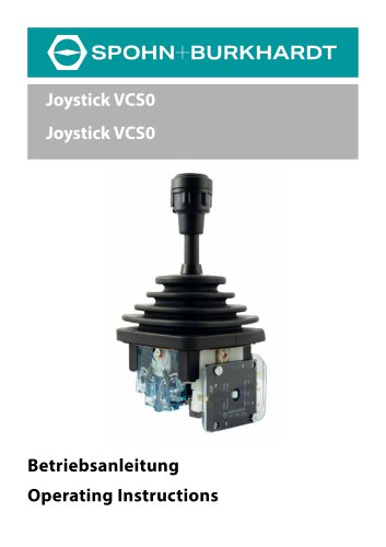
Joystick VCS0
- Documentation: Operating instructions must remain accessible and readable throughout the device's lifespan.
- Intended Use: The device is part of a larger system, requiring the operator to ensure safe operation.
- Personnel: Only trained and authorized personnel should handle the device.
- Safety Notices: Hazards are classified according to ISO 3864-2 and ANSI standards.
- Adhere to five safety rules: disconnect, secure against reconnection, verify absence of voltage, ground and short-circuit, and cover or fence off adjacent live parts.
- Avoid unauthorized modifications and use only original spare parts.
- Use appropriate packaging to protect components during transport.
- Avoid large temperature fluctuations during storage.
- The Joystick VCS0 is robust, suitable for medium-duty applications, with a heat and cold-resistant drive block.
- Optional contacts are integrated for space efficiency.
- Various modules are available for movement direction limitation or guidance.
- Details on joystick specifications, including drive and switching cycles, are provided.
- Mechanical and electrical installation instructions are detailed, including dimensions and mounting options.
- Functional tests for mechanical and electrical components are outlined.
- Regular inspections, cleaning, and lubrication of moving parts are recommended.
- Instructions for replacing standard grips, rubber boots, contact elements, and cam discs are provided.
- Guidelines for electrical disconnection and mechanical disassembly are included.
- Proper disposal methods are advised.
- Examples of variants and available installations, grips, and conformity declarations are provided.
The document provides a detailed technical overview of the Joystick VCS0, including its components, technical specifications, installation procedures, and maintenance guidelines. Key components include the knob, stick, rubber boot, and various internal elements like the contact element and cam disk.
Technical Specifications
The Joystick VCS0 operates within an ambient temperature range of -20°C to +60°C. It has a rated operating voltage of 250V and varying operating currents depending on the load type and voltage. The joystick is designed for a mechanical service life of 10 million switching cycles and supports connections via normal clamps with specific wire cross-sections.
Installation Procedures
Installation must be performed by qualified personnel, adhering to safety regulations. The document outlines mechanical installation steps for different joystick variants, emphasizing the need to disconnect power before starting. Specific instructions are provided for installing the joystick with escutcheon holders and rubber boots.
Electrical Connection
Electrical connections can be made via screw terminals, solder connections, or connectors. The document stresses the importance of correct cable placement and securing connection screws with a specified torque to prevent damage.
Setup and Function Testing
Setup involves conducting mechanical and electrical function tests to ensure proper operation. Damaged joysticks should not be used, and any malfunctions detected during testing require replacement of the joystick.
Servicing and Maintenance
Regular servicing includes visual inspections, cleaning, and checking screw joints. Moving parts should be greased quarterly, and components like knobs, rubber boots, and contact elements should be replaced as needed. The document provides detailed steps for replacing these components.
Safety and Precautions
All tasks must be performed by specialist personnel, with strict adherence to safety instructions outlined in the document. The importance of disconnecting power before servicing and ensuring all components are correctly installed and functioning is emphasized.
- Disconnect electrical power and open installation space.
- Remove joystick VCS0 and contact element as per specified sections.
- Remove screws and locking washers, replace cam disk, and reassemble components.
- Reinstall joystick and undertake setup.
- Adjust braking force using screw; if ineffective, replace brake disk.
- Follow preparatory steps and adjust or replace components as needed.
- Reinstall joystick and undertake setup.
- Repairs should be conducted by Spohn & Burkhardt; removal should be done by specialists.
- Follow specific steps for electrical disconnection and mechanical removal based on joystick variant.
- Dispose of devices according to laws and regulations.
- Reference documents include conformity declarations and product data sheets.
- List of spare parts for joystick VCS0, including various components and their specifications.
- Examples of joystick variants and available fittings, including potentiometers and optical encoders.
The document provides details on various components related to the joystick VCS0, including the boot holder CS092 V0044 and hose clip ZY72x5. It includes a dimension drawing for the joystick VCS0 with a standard knob G41, specifying dimensions in millimeters.
This section lists various knobs available for the joystick VCS0, such as G1, G2, G4T-WT, and G41, among others. It also mentions specific mechanisms like the G41D detent mechanism and G41DR self-return.
The document outlines available capacitive sensors for the joystick VCS0, including the ESS080A evaluation electronics with a power supply of DC 24 V. It lists compatible knobs and notes that further combinations can be found in chapter 11 or by contacting Spohn & Burkhardt.
Available bus systems for the joystick VCS0 include CANopen and USB, with specific installation types and operating voltages detailed. Further combinations can be obtained by contacting the company.
The document includes a declaration of conformity from Spohn & Burkhardt GmbH & Co. KG, providing contact information for the company.
Catalog excerpts
Betriebsanleitung Operating Instructions
Open the catalog to page 1
Impressum Spohn & Burkhardt GmbH & Co. KG Mauergasse 5 89143 Blaubeuren Germany Web: www.spobu.de Mail: [email protected] Schutzvermerk (DIN ISO 16016:2017-08) Weitergabe sowie Vervielfältigung dieses Dokuments, Verwertung und Mitteilung seines Inhalts sind verboten, soweit nicht ausdrücklich gestattet. Zuwiderhandlungen verpflichten zu Schadenersatz. Alle Rechte für den Fall der Patent-, Gebrauchsmuster- oder Designeintragung vorbehalten. Weiterentwicklungen sowie technische Änderungen vorbehalten. Änderungen, Irrtümer und Druckfehler begründen keinen Anspruch auf Schadenersatz. Imprint Spohn &...
Open the catalog to page 2
1. Sicherheit 1.1. Dokumentation Die vorliegende Betriebsanleitung ist Teil des Produktes und enthält alle Informationen zur mechanischen Montage, zum elektrischen Anschluss sowie zu Betrieb und Wartung des Gerätes. Die Betriebsanleitung muss während der Lebensdauer des Gerätes dem jeweiligen Benutzer stets in einem leserlichen Zustand zugänglich sein. 1.2. Bestimmungsgemäße Verwendung Die in dieser Betriebsanleitung beschriebenen Geräte werden als Teil einer Gesamtanlage oder Maschine eingesetzt. Es liegt in der Verantwortung des Betreibers, die sichere und fehlerfreie Gesamtfunktion sicherzustellen....
Open the catalog to page 5
2. Sicherheitshinweise Gefahr durch elektrischen Stromschlag! Beachten Sie vor allen Arbeiten am Gerät die fünf Sicherheitsregeln in der folgenden Reihenfolge: • Freischalten. • Gegen Wiedereinschalten sichern. • Spannungsfreiheit prüfen. • Erden und Kurzschließen. • Benachbarte, unter Spannung stehende Teile abdecken oder abschranken. Gefahr durch unsachgemäß ausgeführte Arbeiten! Durch unsachgemäß ausgeführte Arbeiten und nicht autorisierte Veränderungen am Gerät entstehen Gefahren für Personen und Schäden am Gerät. Spohn & Burkhardt übernimmt keine Haftung für Schäden, die durch unsachgemäß...
Open the catalog to page 6
Achtung! Achten Sie darauf, dass alle Leitungen ordnungsgemäß ohne Knicke und Scheuerstellen verlegt sind. Achten Sie darauf, dass die Leitungsmarkierer nicht entfernt werden bzw. markieren Sie neue Leitungen, sodass eine Zuordnung möglich ist. Fassen Sie die Leitungen ggf. mit Kabelbindern zusammen. Beachten Sie beim Verlegen der Leitungen die ggf. vom Hersteller vorgegebenen Biegeradien. 3. Transport, Verpackung und Lagerung 3.1. Transport und Verpackung Wählen Sie eine geeignete Verpackung, wenn Sie das Gerät selbst oder Komponenten des Gerätes z. B. zur Reparatur senden. Achten Sie besonders...
Open the catalog to page 7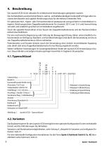
4. Beschreibung Der Joystick VCS0 ist ein robuster, für mittelschwere Anwendungen geeigneter Joystick. Der Antriebsblock aus kriechstromfestem, wärme- und kältebeständigem Isolierstoff ist Träger aller mechanischen Bauteile und zugleich Berührungsschutz für die elektrisch leitenden Teile. Ein optionaler Null-, Hupen- oder Totmannkontakt ist platzsparend und geschützt im Antriebsblock integriert. Berührungssichere Doppelkontaktelemente für maximal 250 V und 10 A sind formschlüssig verrastet und zusätzlich gesichert am Antriebsblock angeflanscht. Durch die spezielle Konstruktion ist der Tausch...
Open the catalog to page 8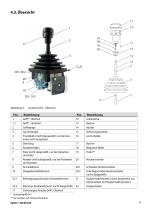
Abbildung 2. Joystick VCS0 - Ubersicht
Open the catalog to page 9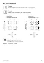
4.4.3. Joystick VCS0 Antrieb Hinweis Beachten Sie die Blickrichtung bei folgenden Griffen: G1, G13, UGN, UGA. Hinweis Fehlt die Angabe der Ausführung, wird Anordnung U geliefert. Blickrichtung Viewing direction Blickrichtung Viewing direction Anbaurichtung Potentiometer/Geber Mounting direction potentiometer/encoder Abbildung 3.
Open the catalog to page 11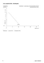
4.4.4. Joystick VCS0 – Schaltspiele Schaltspiele im Mio. Schaltstück – Lebensdauer mit AG-Kontakten AC 24 V (ohmsche Last AC 230 V
Open the catalog to page 12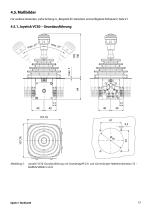
4.5. Maßbilder Für weitere Varianten, siehe Anhang A. „Beispiele für Varianten und verfügbare Einbauten“, Seite 41. Joystick VCS0 Grundausführung mit Standardgriff G41 und Gummistulpe-Halterkombination S3 – Maßbild (Maße in mm)
Open the catalog to page 13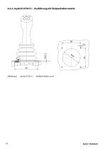
4.5.2. Joystick VCS0 S1 – Ausführung mit Stulpenhalterrosette Joystick VCS0 S1… – Maßbild (Maße in mm)
Open the catalog to page 14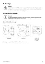
5. Montage Gefahr! Alle Arbeiten am Gerät dürfen nur von Fachpersonal und unter Berücksichtigung der einschlägigen Sicherheitsvorschriften durchgeführt werden. Beachten Sie grundsätzlich die Sicherheitshinweise in Kapitel 1. „Sicherheit“, Seite 5. 5.1. Mechanische Montage Hinweis Die Montage erfolgt von unten durch die Einbauplatte. Bei Varianten mit großen Griffen (z. B. T-Griff ) muss der Griff demontiert werden. Joystick VCS0 …: Maße Einbauöffnungen (Maße in mm)
Open the catalog to page 15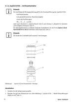
5.1.2. Joystick VCS0… mit Rosettenhalter Hinweis Die nachfolgende Montageanleitung gilt für die Grundausführung des Joysticks VCS0: • mit Potentiometer, • mit optoelektronischem Absolutwertgeber • sowie die Ausführungen • 96…; 72…; S…; und S0…. siehe auch Abschnitt 4.1 „Typenschlüssel“, Seite 8 und Anhang A. „Beispiele für Varianten und verfügbare Einbauten“, Seite 41. Für Montagehinweise zu weiteren Varianten kontaktieren Sie die Firma Spohn & Burkhardt GmbH & Co. KG (Kontaktdaten siehe Impressum, Seite 2). Hinweis Die Stärke der Schalttafel darf maximal 5 mm betragen. Joystick VCS0 mit Rosettenhalter...
Open the catalog to page 16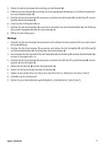
3. Ziehen Sie die Gummistulpe (3) vorsichtig von der Rosette (8). 4. Entfernen Sie die Rosette (8) vorsichtig mit einem geeigneten Werkzeug (z. B. Schlitzschraubendre-her) vom Rosettenhalter (6). 5. Drucken Sie die Gummistulpe (3) zusammen und ziehen Sie die Rosette (8) und die Folie (7) vorsichtig uber die Gummistulpe (3). 7. Drucken Sie die Gummistulpe (3) zusammen und ziehen Sie den Rosettenhalter (6), die Dichtung (5) und die Frontplatte (4) uber die Gummistulpe (3). 1. Drucken Sie die Gummistulpe (3) zusammen und schieben Sie den Joystick VCS0 von unten durch die Einbauoffnung. 2. Drucken...
Open the catalog to page 17All Spohn & Burkhardt GmbH & Co. KG catalogs and technical brochures
 FSMMD Ultra Smart
12 Pages
 ST1
ST14 Pages


Archived catalogs
 Ship and harbour resistors
8 Pages
 Industry Control systems
8 Pages
 Industry Resistors
8 Pages
 Brochure image
32 Pages