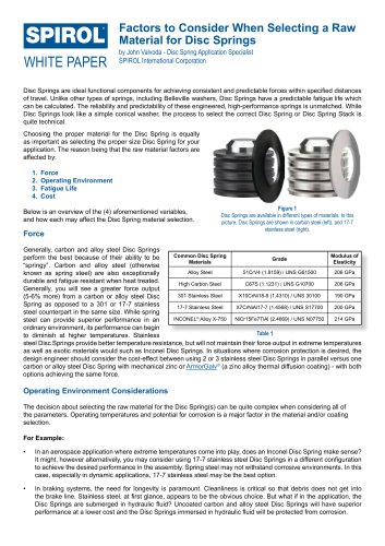
How to Design the Optimum Hinge

How to Design the Optimum Hinge
This document discusses the design and application of hinges, focusing on two primary types: free fit hinges and friction fit hinges. It highlights the use of Coiled Spring Pins in both types and provides guidelines for optimal hinge performance.
Types of Hinges
Free Fit Hinges: These hinges allow components to rotate freely with minimal friction. The Coiled Pin's diameter is determined by the smallest retaining hole, and the design should minimize the gap between components to reduce clearance and prevent pin bending.
Friction Fit Hinges: These require interference to prevent free rotation. All holes should be sized identically within tolerances, and Coiled Pins are preferred for their ability to maintain alignment and performance.
Design Guidelines
For free fit hinges, establish the maximum hole size in the retaining component and measure the pin's free diameter at the center of the span. Add clearance and production tolerance to determine the free hole's diameter. For friction fit hinges, ensure all holes are sized identically or split the tolerance between components.
Recommendations
Consult with Application Engineers for specialized fastening and joining solutions. SPIROL offers engineering support to ensure optimal hinge design.
Additional Resources
SPIROL provides Coiled Pins in various duty levels and offers a Rapid Search page for more information. For technical support, contact SPIROL or visit their website.
Catalog excerpts
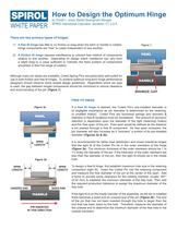
How to Design the Optimum Hinge by Christie L. Jones, Market Development Manager SPIROL International Corporation, Danielson, CT, U.S.A. WHITE PAPER There are two primary types of hinges: 1) A free fit hinge has little to no friction or drag when the latch or handle is rotated. Hinge components are “free” to rotate independent of one another. Figure 1 2) A friction fit hinge requires interference to prevent free rotation of components relative to one another. Depending on design intent, resistance can vary from a slight drag to a value sufficient to maintain the fixed position of components anywhere in their full range of rotation. PAWL Although many pin styles are available, Coiled Spring Pins are particularly well suited for use in both friction and free fit hinges. To achieve optimum long-term hinge performance designers should observe some simple design guidelines. Regardless which pin type is used, the gap between hinged components should be minimized to reduce clearance and avoid bending of the pin (Figure 1). HANDLE MINIMIZE GAP FREE FIT HINGE If a free fit hinge is desired, the Coiled Pin’s pre-installed diameter is of negligible importance as pin diameter is determined by the retaining, or smallest hole(s). Coiled Pins are functional springs and recovery & retention in free fit locations must be considered. The amount of recovery/ retention is dependant upon the diameter of the tight (retaining) hole(s) and the ‘free span’ of the pin. Free span would be defined as the distance a pin passes through a free fit component. As free span increases, the pin diameter will also increase as it “recovers” a portion of its pre-installed diameter (Figures 2a & 2b). Figure 2a PAWL It is recommended for better load distribution and closer tolerance hinges that the tight fit of the Coiled Pin be in the outer members of the hinge (Figure 2a). The minimum thickness of the outer members should be 1 to 1½ times the diameter of the pin. If the thickness of the outer members are less than the diameter of the pin, then the tight fit should be in the inside hole. SPAN LENGTH Figure 2b SPAN LENGTH SPAN LENGTH UNSIZED END SIZED END HANDLE PIN INSERTED IN THIS DIRECTION To design a free fit hinge, first establish maximum hole size in the retaining component (tight fit). Insert the Coiled Pin into the retaining component and measure the free diameter of the pin at the center of the span. Add a factor to provide some clearance for the rotating member, usually .001” (0.02 mm) to establish the minimum diameter of the free hole. Then add the required production tolerance to assign the maximum diameter of the free hole. If the tight fit is on the inside member of the assembly, as the pin is installed there becomes a sized and an unsized end of the pin (Figure 2b). The end of the pin that has not been inserted through the hole is larger than the end that has been sized by the hole. Therefore, measure the diameter of the unsized end to determine the minimum diameter of the free hole in the outside members.
Open the catalog to page 1
U.S.A. FRICTION FIT HINGE In a friction fit hinge, all of the holes should be sized identically within the assigned tolerances. If the manufacturer is unable to maintain the same hole size within each component, the tolerance should be split between the components. It is most common to assign the smaller half of the tolerance to the outside holes and larger half to the inside hole. Spirol International Corporation 30 Rock Avenue Danielson, Connecticut 06239 Tel. +1 860.774.8571 Fax. +1 860.774.2048 (US Distributors: Fax. +1 860.774.0487) Spirol International Corporation Shim Division 321 Remington...
Open the catalog to page 2All SPIROL catalogs and technical brochures
 SPIROL Corporate Brochure
12 Pages
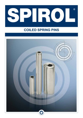 Coiled Spring Pins
24 Pages
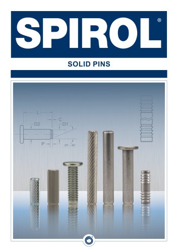 Solid Pins
12 Pages
 Alignment Dowels/Bushings
12 Pages
 Compression Limiter Design Guide
20 Pages
 Slotted Spring Pins
16 Pages
 Latch Pins for Plastics
2 Pages
 Railroad Nuts - AAR Series
2 Pages
 Disc Springs
20 Pages
 Installation Technology
8 Pages
 Series RH600 Twist-Lok™ Pins
2 Pages
 Cosmestic Pins 550 series
2 Pages
 SPIROL Precision Shims
8 Pages
 Medical Device Applications
2 Pages
 Series 2000 Series 2000
4 Pages
 Aerospace Applications Flyer
2 Pages
 Tables Lift and Roll
2 Pages
 Tables Standard
2 Pages
 SPD, CXA, CXD, CXE CRD
2 Pages
 HC series HC series
2 Pages
 PH series PH series
2 Pages
 880 Series
2 Pages


- Chuck
- Feeder
- SPIROL metal insert
- SPIROL threaded insert
- Mounting machine
- Automated feeder
- SPIROL round insert
- Drilling chuck
- Round washer
- Metal washer
- Automatic assembling machine
- SPIROL metal pin
- Drilling tool holder
- Vibrating feeder
- SPIROL brass insert
- Steel washer
- SPIROL plastic insert
- Knurled insert
- SPIROL steel pin