Disc Springs

Disc Springs
Disc Springs are conically-shaped components designed for axial loading, adhering to DIN EN 16984 standards. They offer high load capacity, space efficiency, consistent performance, and extended fatigue life, and can be used singly or in stacks.
Key dimensions include external diameter (De), internal diameter (Di), free height (lo), material thickness (t), and free cone height (ho). Important parameters are force (F), deflection (s), stress (σ), modulus of elasticity (E), and Poisson’s ratio (μ).
SPIROL provides Disc Springs conforming to DIN EN 16983 standards, with custom sizes and materials available. They are categorized into Series A, B, and C based on material thickness and force/deflection characteristics.
The load/deflection curve is non-linear, influenced by the cone height to thickness ratio (ho/t). Ratios above 1.5 require careful consideration to prevent inversion.
Disc Springs can handle static and dynamic loads. Static loading involves constant or occasionally changing loads, while dynamic loading involves cyclic applications. Monitoring critical stress points is essential to avoid permanent deformation.
Estimating fatigue life involves selecting appropriate configurations and calculating stresses at critical points. A preload of 15%-20% is recommended to enhance fatigue life.
Material selection is crucial, with high carbon and alloy steels offering strength and endurance. Stainless steels provide corrosion resistance but have limitations in dynamic applications. Proper sizing, orientation, and stack configuration optimize performance and longevity.
Using the largest practical outside diameter discs minimizes the number of discs and stack height. Total stack height should not exceed three times the external disc diameter or ten total discs. Lubrication is essential for efficiency and longevity, with solid lubricants for moderate applications and oil or grease for severe conditions.
Stacking methods include parallel, series, and combination stacking. Lubrication is necessary, and the number of discs in a parallel set should be limited to four to reduce deviations. Guiding stacks with a rod or sleeve is recommended to maintain disc position.
Details on load and deflection characteristics include progressive load curves and the importance of preload and deflection limits. Shot peening is used to induce compressive stresses and improve fatigue life.
Dimensional tolerances for disc springs include diameter, thickness, and concentricity tolerances, with specific values provided in tables.
Standard materials include high carbon steel and alloy steel, with specific hardness values. The standard finish is phosphate coated and oiled.
Ordering format includes product code, dimensions, material code, and finish code.
The document details technical specifications and applications for SPIROL® Disc Springs in industrial applications like braking systems, pipe supports, and CNC machines. It includes data on dimensions, design force, deflection, and stresses, highlighting the benefits over traditional springs.
Detailed measurements and performance metrics include preload, deflection, and stress values based on material properties (E = 190 kMPa and µ = 0.3), with a comprehensive table of dimensions and forces for different configurations.
- Braking Systems: Used as a mechanical backup in hydraulic braking systems for reliability.
- Pipe Supports: Maintain constant pressure in piping systems to accommodate thermal changes.
- CNC Machines: Provide consistent clamping force for precision and reliability.
SPIROL® Disc Springs offer high energy storage capacity, predictable performance, and space efficiency. They can be stacked in series or parallel to meet specific force and travel requirements.
Contact details for SPIROL's offices worldwide are provided, offering support and engineering services.
Catalog excerpts

DISC SPRINGS
Open the catalog to page 1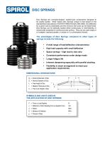
DISC SPRINGS Disc Springs are conically-shaped, washer-type components designed to be axially loaded. What makes Disc Springs unique is that based on the standardised calculations of DIN EN 16984 (formerly DIN 2092), the deflection for a given load is predictable and the minimum life cycle can be determined. Disc Springs can be statically loaded either continuously or intermittently, or dynamically subjected to continuous load cycling. They can be used singly or in multiples, stacked parallel, in series or in a combination thereof. The advantages of Disc Springs compared to other types of springs...
Open the catalog to page 2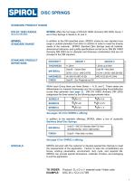
DISC SPRINGS STANDARD PRODUCT RANGE DIN EN 16983 RANGE SPIROL offers the full range of DIN EN 16983 (formerly DIN 2093) Group 1 and 2 Disc Springs in Series A, B, and C. SPIROL STANDARD RANGE In addition to the DIN specified sizes, SPIROL stocks its own standard size range in outside diameters from 8mm to 200mm in order to meet the diverse needs of the customer. SPIROL Standard Disc Springs meet all material, dimensional tolerance, and quality specifications as laid out in DIN EN 16983 (formerly DIN 2093) but in diameter and thickness combinations that are not included in the DIN standard. STANDARD...
Open the catalog to page 3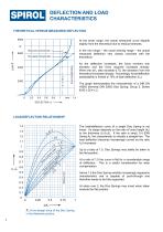
DEFLECTION AND LOAD CHARACTERISTICS THEORETICAL VERSUS MEASURED DEFLECTION 8000 At the lower range, the actual measured curve departs slightly from the theoretical due to residual stresses. In the mid range – the usual working range – the actual measured deflection very closely coincides with the theoretical. Measured Characteristic As the deflection increases, the force moment arm shortens and the force required increases sharply. When the s/ho ratio exceeds 0.75, the deviation from the theoretical increases sharply. Accordingly, force/deflection predictability is limited to 75% of total deflection...
Open the catalog to page 4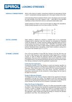
LOADING STRESSES CRITICAL STRESS POINTS When a Disc Spring is loaded, compressive stresses are generated at Points I and IV. Compressive stresses typically act on the upper surface of the Disc. At the theoretical Point (0) between Points I and IV, the stress must not exceed the yield strength of the Disc material (1,400 – 1,600 MPa for the specified materials) to ensure that there will be no permanent deformation (set). Tensile stresses at Points II and III are the basis for fatigue life calculations. Tensile stresses typically act on the lower surface of the Disc. STATIC LOADING Static loading...
Open the catalog to page 5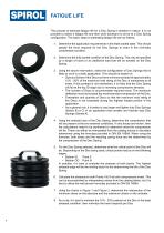
FATIGUE LIFE The process to estimate fatigue life for a Disc Spring is iterative in nature. It is not possible to select a fatigue life and then work backward to arrive at a Disc Spring configuration. The basic steps to estimating fatigue life are as follows: 1. Determine the application requirements in the least loaded state. This should specify the force required for the Disc Springs to exert in the minimally compressed condition. 2. Determine the fully loaded condition of the Disc Spring. This may be specified by a length of travel or an additional load that will be exerted on the Disc Spring....
Open the catalog to page 6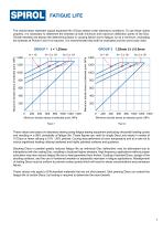
FATIGUE LIFE The charts below represent typical expected life of Discs tested under laboratory conditions. To use these charts properly, it is necessary to determine the stresses at both minimum and maximum deflection points of the Disc. Tensile stresses are always the determining factor in causing failure due to fatigue, so as a minimum, evaluating the stresses at Points II and III is required. It is recommended that both be evaluated and the worst case used. GROUP 2 1.25mm ≤ t ≤ 6.0mm Maximum tensile stress at selected point, MPa Maximum tensile stress at selected point, MPa These values are...
Open the catalog to page 7
DESIGN GUIDELINES SIZING AND SELECTION ● Select the disc with the largest outside diameter (De). This reduces the stresses at a given force (F)/deflection (s) ratio and thus enhances fatigue life. An outside (De) to inside diameter (Di) of 1.7 to 2.2 also enhances performance and longevity. ● Thicker discs have greater damping (hysteresis) characteristics. Fatigue life can be improved by increasing preload and reducing maximum deflection. This will likely require additional discs in series, but will extend life. Shot peening induces favourable compressive stresses on the disc surface. This reduces...
Open the catalog to page 8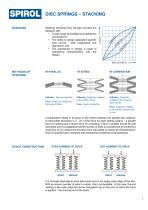
Stacking individual Disc Springs provides the designer with: • A wide range of possible force/deflection combinations; • The ability to design application specific load curves – both progressive and regressive; and • The opportunity to design a range of dampening characteristics into the design. DISC SPRINGS – STACKING Deflection: Same as single Disc Force: Single Disc multiplied by the number of Discs Deflection: Single Disc multiplied by the number of Discs Force: Same as single Disc Deflection: Single Disc multiplied by the number of Discs in series Force: Single Disc multiplied by the number...
Open the catalog to page 9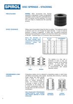
DISC SPRINGS – STACKING PRE-STACKED SPIROL offers pre-stacked Disc Springs (greased or ungreased) in custom configurations packaged in shrink wrap with a perforated tab for ease of insertion into the assembly. This saves time and helps to mistake-proof the assembly process. STACK GUIDANCE Stacks need to be guided to keep the discs in position. The preferred method is internal, such as a rod through the inside diameter. In case of external guidance, a sleeve is suggested. In either case, the guiding component should be case-hardened to a depth of not less than 0.6mm and a hardness of 58 HRC. A...
Open the catalog to page 10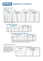
DIMENSIONAL TOLERANCES DIAMETER TOLERANCE Outside Diameter: Inside Diameter: De or Di RANGE Over Over Over Over Over Over Over Over 1) In reference to Outside Diameter De THICKNESS TOLERANCE (t) TOLERANCE mm FREE OVERALL HEIGHT (lo) TOLERANCE* TOLERANCE mm Less than From * Per DIN EN 16893 (formerly DIN 2093), it is permissible to exceed standard tolerance for lo in order to comply with spring load requirements. SPRING FORCE TOLERANCE The static load (F) of a single disc shall be determined for a disc in the loaded state using a suitable lubricant. The pressure plates between which the disc is...
Open the catalog to page 11All SPIROL catalogs and technical brochures
 SPIROL Corporate Brochure
12 Pages
 Coiled Spring Pins
24 Pages
 Solid Pins
12 Pages
 Alignment Dowels/Bushings
12 Pages
 Compression Limiter Design Guide
20 Pages
 Slotted Spring Pins
16 Pages
 Latch Pins for Plastics
2 Pages
 Railroad Nuts - AAR Series
2 Pages
 Installation Technology
8 Pages
 Series RH600 Twist-Lok™ Pins
2 Pages
 Cosmestic Pins 550 series
2 Pages
 SPIROL Precision Shims
8 Pages
 Medical Device Applications
2 Pages
 Series 2000 Series 2000
4 Pages
 Aerospace Applications Flyer
2 Pages
 Tables Lift and Roll
2 Pages
 Tables Standard
2 Pages
 SPD, CXA, CXD, CXE CRD
2 Pages
 HC series HC series
2 Pages
 PH series PH series
2 Pages
 880 Series
2 Pages


- Chuck
- Feeder
- SPIROL metal insert
- SPIROL threaded insert
- Mounting machine
- Automated feeder
- SPIROL round insert
- Drilling chuck
- Metal washer
- Round washer
- SPIROL pin
- SPIROL metal pin
- Automatic assembling machine
- Drilling tool holder
- Vibrating feeder
- Steel washer
- SPIROL brass insert
- SPIROL plastic insert
- Knurled insert
- SPIROL steel pin