


Compression Limiter Design Guide
Compression Limiter Design Guide
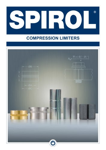
Compression Limiters are crucial in plastic assemblies to maintain joint integrity by absorbing compressive loads from tightened bolts, preventing damage to plastic components and ensuring assembly longevity.
- Material Compatibility: Consider the type of plastic, its thickness, fastener size, and torque requirements.
- Joint Integrity: Ensure the bolt head or washer seats against both the plastic host and the Compression Limiter to prevent load deterioration due to plastic creep.
- Proof Load: The Compression Limiter's proof load should match or exceed the bolt's proof load to prevent yielding under excessive loads.
- Component Strength: The mating component must withstand localized compressive stresses.
- Clearance: Adequate clearance between the bolt and the Compression Limiter is necessary to accommodate assembly tolerances.
SPIROL offers a variety of Compression Limiters, including formed and machined types, designed for specific applications and proof loads. They provide corrosion resistance and are available in materials like high carbon steel, aluminium, and brass.
- CL220 Split Seam: High carbon steel, post-mould installation, ArmorGalv® coating, suitable for ISO Class 8.8 bolts.
- CL200 Slim Profile: Similar to CL220 but with a smaller inner diameter and reduced profile.
- CL350 Heavy Wall: Thicker wall for increased bearing surface, suitable for ISO Class 10.9 bolts.
- CL400 Oval: Provides extra clearance on one axis, cost-effective, suitable for ISO Class 8.8 bolts.
- CL460 Moulded-In Oval: Butted-seam design to prevent plastic intrusion, suitable for ISO Class 8.8 bolts.
- CL500 Moulded-In: Low carbon steel, anti-rotation feature, suitable for ISO Class 8.8/Grade 5 bolts.
- CL6000 Precision Machined Aluminium: Lightweight, lead-free, suitable for ISO Class 10.9/Grade 8 bolts.
- CL6100 Headed Aluminium: Similar to CL6000 with an added head for extra bearing surface.
- CL8000 Precision Machined Brass: Larger wall thickness for more bearing surface, suitable for ISO Class 10.9/Grade 8 bolts.
- CL8100 Headed Brass: Similar to CL8000 with an added head.
- CL620 General Purpose Aluminium: For non-critical applications, lightweight and lead-free.
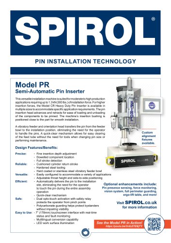
SPIROL provides various installation machines, including semi-automatic and manual options, ensuring accurate and consistent installation of Compression Limiters.
- All components in the load path must sustain the fastening load under all conditions.
- Metal Compression Limiters are necessary due to plastic's stress and strain relaxation.
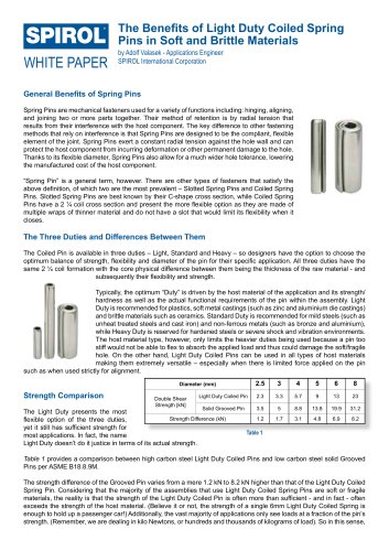
- Recommended bolt load is 25% to 75% of proof load to ensure adequate frictional retention without exceeding the bolt's proof load.
The length of the Compression Limiter should match the minimum thickness of the plastic component to ensure proper load application and prevent creep.
The document outlines specifications for Compression Limiters, focusing on load ratings and maintaining the integrity of both the Limiter and the plastic host. It emphasizes that Compression Limiters are rated by the load required to compress them to a safe distance, ensuring the integrity of the bolted connection and preventing stress relaxation.
- Ensure the boss diameter is twice the Compression Limiter diameter and that the wall thickness prevents bulging or cracking.
- Select the appropriate bolt class and tightening torque to avoid unnecessary costs and ensure assembly integrity.
- Ensure the bolt is tightened to 75% of its proof load, proper alignment of the Limiter with the Insert, and correct hole size for retention.
- The host material must absorb the clamp load and withstand compression forces.
Detailed tables provide dimensions for nominal bolt sizes ranging from M3 to M10, including inner diameter, body diameter, knurl diameter, head diameter, and recommended hole sizes. Length tolerances and wall thicknesses are also specified.
Each series of compression limiters is rated for specific ISO Class bolts, with options for special lengths and sizes upon request. The document emphasizes consulting SPIROL Engineering for adjustments when using thicker finishes.
SPIROL® Compression Limiters can be installed using SPIROL Installation Equipment or pressed in. The document provides ordering instructions and examples for each series.
The document lists contact details for SPIROL offices worldwide, offering support for application engineering and design assistance.
Catalog excerpts
COMPRESSION LIMITERS
Open the catalog to page 1
THE FUNCTION OF A COMPRESSION LIMITER The primary function of a Compression Limiter is to provide and maintain joint integrity of a plastic assembly. Compression Limiters are designed to protect the plastic components of an assembly from the compressive loads generated by the tightening of bolts, thereby assuring continued integrity of the bolted connection. In practice, the Compression Limiter should be slightly shorter than the thickness of the plastic host. As the bolt is tightened the plastic compresses and the stress in the plastic increases until the head of the bolt, or washer if one is...
Open the catalog to page 2
SPIROL’S COMPRESSION LIMITERS SPIROL offers a range of both formed and machined Compression Limiters including split seam, moulded in, oval and solid wall designs. All formed Compression Limiters, except the Series CL220, are zinc plated and have a supplementary coating of trivalent passivation and an organic sealant for corrosion resistance. This finish provides 144 hours to white corrosion, and 384 hours to red corrosion when salt spray tested in accordance with ASTM B117. SPIROL’s Series CL220 Compression Limiters are coated with ArmorGalv®, a zinc alloy thermal diffusion coating complimented...
Open the catalog to page 3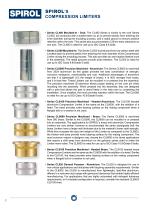
SPIROL’SCOMPRESSION LIMITERS • Series CL460 Moulded-In - Oval: The CL460 Series is similar to the oval Series CL400, but produced with a butted-seam so as to prevent plastic from entering the inner diameter during the moulding process, and a radial groove to ensure positive retention within the hole. This series also accommodates 2.25mm extra clearance on one axis. The CL460 is rated for use up to ISO Class 8.8 bolts. • Series CL500 Moulded-In: The Series CL500 is produced from low carbon steel with a butted seam to prevent plastic from entering the inner diameter of the Compression Limiter during...
Open the catalog to page 4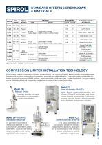
STANDARD OFFERING BREAKDOWN & MATERIALS SERIES Other diameters available upon request. Install one or multiple Compression Limiters simultaneously into various polymers, thermoplastics and/or thermosets. Options such as vision sensing for part presence, automatic fixture identification, customised rotary or linear fixture motion, password protection of HMI screens, keyed reset, status/indicator lights, audible fault alarm, and part marking can be added for enhanced productivity, heightened process control and error-proofing. Semi-Automatic Multi-Tip For larger assemblies and components outside...
Open the catalog to page 5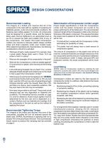
DESIGN CONSIDERATIONSRecommended Loading The integrity of a bolted joint requires that all of the components in the load path be capable of sustaining for indefinite periods, under all environmental conditions, the fastening load initially applied. To do this, all components must be designed for a specific stress, and the fastener being used must be tightened to an appropriate level so as not to exceed the yield point (elastic limit) of any of the components. The reason that metal Compression Limiters are required is because plastic always exhibits stress and strain relaxation under even modest...
Open the catalog to page 6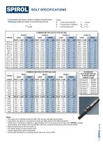
BOLT SPECIFICATIONS Typical tightening torque values to achieve recommended Clamping Loads are based on the following formula: Where: D = nominal bolt diameter K = torque-friction coefficient P = bolt clamping load COMMON METRIC BOLTS PER ISO 898 STANDARD FASTENER RATING: STRESS UNDER PROOF LOAD Notes: • Inch sizes are not directly covered by SAE J429, but are calculated appropriately. • Calculations are based on using bolt proof loads per SAE J429 and ISO 898 respectively. • Clamp load in calculation is based on approximately 75% of the proof load for each bolt. SPIROL strongly recommends not...
Open the catalog to page 7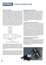
DESIGN CONSIDERATIONS Plastic Host Design Mating Component Material Although the Split Seam Compression Limiters have a broken edge, this is kept to a minimum in order to maintain the maximum bearing surface area. Accordingly, it is recommended that a radius be moulded as a lead-in to the hole in the plastic component to facilitate insertion. This radius is not necessary for Solid Wall Compression Limiters as the pilot is smaller than the hole. The hole should taper within the recommended hole size for the length of the Compression Limiter. Hosts for Split Seam Compression Limiters must be within...
Open the catalog to page 8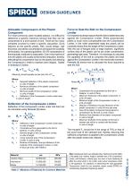
DESIGN GUIDELINES SPIROLAllowable Compression of the Plastic Component For most commonly used moulded plastics, it is difficult to determine a specific maximum amount that they can be compressed in a short period of time. There are too many variables involved to make a specific calculation. Such features as the specific plastic, filler, mould design, wall thickness, and stress concentrations all impact the durability of the plastic. As a general guideline, 3%-5% compression of thermoplastic materials is reasonable. Over a short period of time the plastic will usually exhibit stress relaxation,...
Open the catalog to page 9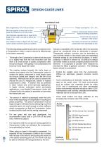
DESIGN GUIDELINES Ideal Bolted Joint Bolt is tightened to 75% of its proof load. Bolt head applies a clamp load on the plastic and bottoms out on the Limiter. Limiter is compressed between bolt’s head and mating component. Host thickness is greater than or equal to the length of the Limiter, and able to absorb the clamp load. Correct hole size ensures retention of the Limiter. The mating component can withstand compression force generated by bolt. The installed Limiter is aligned with the Insert (when used) to prevent a jack-out condition. The following design guidelines should be considered...
Open the catalog to page 10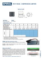
SPLIT SEAM - COMPRESSION LIMITERSSeries CL220 DIMENSIONAL DATA MATERIAL FINISH B High Carbon Steel H ArmorGalv® • CL220 rated for use up to ISO Class 8.8 bolts. • Special lengths and sizes available upon request. • Please reference pages 4-8 for design considerations and guidelines. SPIROL® Split Seam Compression Limiters can be installed with SPIROL Installation Equipment or simply pressed in. To Order: CMPL, Nominal Bolt Diameter, Length, Material, Finish, Series Example: CMPL 6 X 6 BH CL220 ArmorGalv® is a zinc alloy thermal diffusion coating covered by ASTM A1059M-08(2013). ArmorGalv® provides...
Open the catalog to page 11All SPIROL catalogs and technical brochures
 SPIROL Corporate Brochure
12 Pages
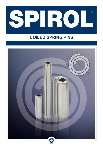 Coiled Spring Pins
24 Pages
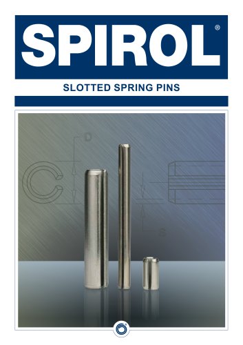 Slotted Spring Pins
16 Pages
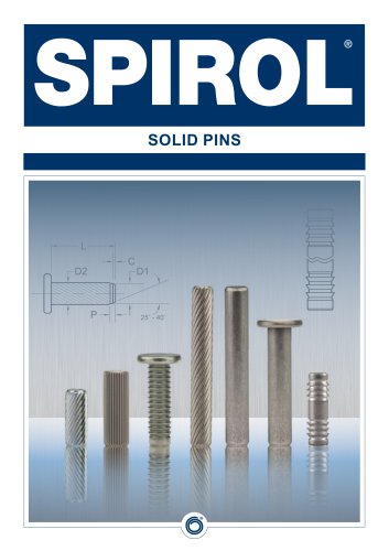 Solid Pins
12 Pages
 Alignment Dowels/Bushings
12 Pages
 Disc Springs
20 Pages
 Installation Technology
8 Pages
 SPIROL Precision Shims
8 Pages
 Series 2000 Series 2000
4 Pages
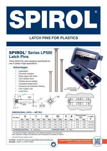 Latch Pins for Plastics
2 Pages
 Railroad Nuts - AAR Series
2 Pages
 Series RH600 Twist-Lok™ Pins
2 Pages
 Cosmestic Pins 550 series
2 Pages
 Medical Device Applications
2 Pages
 Aerospace Applications Flyer
2 Pages
 Tables Lift and Roll
2 Pages
 Tables Standard
2 Pages
 SPD, CXA, CXD, CXE CRD
2 Pages
 HC series HC series
2 Pages
 PH series PH series
2 Pages
 880 Series
2 Pages







- Chuck
- Feeder
- SPIROL metal insert
- SPIROL threaded insert
- Mounting machine
- Automated feeder
- SPIROL round insert
- Drilling chuck
- Metal washer
- Round washer
- SPIROL pin
- SPIROL metal pin
- Automatic assembling machine
- Drilling tool holder
- Vibratory feeder
- Steel washer
- SPIROL brass insert
- SPIROL plastic insert
- Knurled insert
- SPIROL steel pin