

BROADCAST

BROADCAST
This document provides technical specifications and guidelines for SPINNER's broadcast products, focusing on high-frequency performance. The information is preliminary and subject to confirmation through a written offer from SPINNER.
The document explains the calculation of maximum permissible output voltage and power for multi-channel combiners. It emphasizes the importance of adding peak voltages of individual signals rather than calculating from combined power. A safety margin of 20% is recommended. The power ratings are RMS figures, and adjustments may be necessary for adjacent channel operations.
Specifications for bandpass filters are provided, including tuning to specific channel bandwidths and mask requirements. The document advises specifying all planned operating frequencies to ensure optimal matching.
Details on environmental conditions for broadcast products are included, ensuring that products meet necessary standards for operation.
The document contains extensive tables listing part numbers, channel spacing, filter specifications, and power ratings for various combiners and filters. Key data includes permissible power levels and mask filtering requirements for different broadcast standards such as DAB, T-DMB, and DTV.
SPINNER provides a range of combiners and filters designed to optimize broadcast performance while adhering to technical specifications and environmental standards. Users are encouraged to consult the latest updates on SPINNER's website.
- Starpoint and Manifold Combiners: These use band pass filters to isolate transmitters and require precise matching networks for optimal performance.
- CIB Combiners: Offer good isolation and broadband matching, allowing for flexible channel configurations. They are preferred for multi-channel setups due to their ease of modification.
- Stretch Line Combiners: Utilize differences in wavelength for signal routing, suitable for channels with more than three-channel spacing.
- Frequency Range: 470 - 860 MHz
- Channel Spacing: ≥ 1
- Temperature Stability: ≤ 2 kHz / K for manifold combiners, ≤ 10 kHz / K for CIB combiners
- Harmonics Attenuation: ≥ 50 dB for frequencies ≤ 1400 MHz or 1500 MHz depending on the model
- Average Input Power: Varies by model and channel width, e.g., 130 W per input for 8 MHz channels in some manifold combiners
- Insertion Loss: Detailed for various frequency offsets, with specific dB ranges provided
- Isolation Between Inputs: ≥ 25 dB to ≥ 35 dB depending on the model
- VSWR: ≤ 1.2 for manifold combiners, ≤ 1.1 for CIB combiners
- Compact 19" slide-in units available in various RU sizes
- Integrated mask filters for DTV
- Wall mount options available for CIB combiners
- Various front plate designs and port configurations
- Frequency Range: 470 - 860 MHz
- Channel Bandwidths: 6, 7, and 8 MHz
- Filter Type: Integrated cavities with various sizes (e.g., 6/38, 8/40, 6/60)
- Temperature Stability: ≤ 2 kHz/K
- Harmonics Attenuation: ≥ 50 dB for frequencies up to 1340 MHz
- Average Input Power: Ranges from ≤ 150 W to ≤ 1.5 kW depending on the model
- Peak Output Voltage: Up to 8.5 kV
- Isolation Between Inputs: ≥ 35 dB
- VSWR: ≤ 1.06 for one wideband channel
- Compact design as a 19" slide-in unit
- Integrated mask filters for DTV
- Temperature compensated and tuneable within the UHF range
- Suitable for adjacent channel operation
- Insertion Loss: Varies with frequency and filter type, generally ≤ 1.5 dB
- Group Delay Variation: Ranges from ≤ 90 ns to ≤ 660 ns
- Environmental Conditions: Specific limitations are detailed in the "Environmental Conditions for Broadcast Products" section
- Power at the wideband input should be reduced by 50% of the power fed into the narrowband input
- Alternative tuning is available upon request
- Dimensions vary by model, e.g., 363 x 483 x 90 mm (2RU) to 900 x 226 x 965 mm
- Weight ranges from approximately 10 kg to 40 kg
- Frequency Range: 470 - 860 MHz
- Channel Bandwidth: Supports 6, 7, and 8 MHz
- Input Types: Narrow band input (7-16 female, 1 5/8" SMS unflanged) and wide band input (1 5/8" EIA, 3 1/8" EIA male)
- Average Input Power: Varies by model, up to 7 kW for wide band input
- Peak Output Voltage: Up to 12.5 kV depending on the model
- Isolation Between Inputs: ≥ 35 dB
- VSWR: ≤ 1.06 for one WB channel
- Temperature Stability: ≤ 2 kHz/K
- Harmonics Attenuation: ≥ 50 dB for frequencies ≤ 950 MHz
- The power at the wide band input must be reduced by 50% of the power fed into the narrow band input.
- Environmental conditions and limitations are specified under "Environmental Conditions for Broadcast Products."
- Integrated mask filters for DTV with temperature compensation.
- Insertion loss and mask filtering are specified with alternative tuning available on request.
- Group delay variation is specified for different standards.
- Compact design suitable for 19" slide-in units.
- Supports adjacent channel operation and is tuneable within the entire UHF range.
- Frequency Range: 470 - 860 MHz
- Channel Spacing: ≥ 0
- Narrow Band Input: 1 5/8" EIA
- Filter Type: Integrated cavities with various sizes (e.g., 6/150, 8/170)
- Temperature Stability: ≤ 2 kHz/K
- Harmonics Attenuation: ≥ 50 dB for frequencies ≤ 860 MHz
- Average Input Power: Varies by model, up to 7 kW for narrow band inputs and up to 60 kW for wide band inputs
- Peak Output Voltage: Ranges from ≤ 8.5 kV to ≤ 19.5 kV depending on the connector type
- Isolation Between Inputs: ≥ 35 dB
- VSWR (Voltage Standing Wave Ratio): ≤ 1.06 for one wide band channel
- Tuning Instructions: Specific instructions provided for different models (e.g., AS6193, AS8071)
- Insertion Loss & Mask Filtering: Alternative tuning available on request
- Group Delay Variation: Specified for different models, ranging from ≤ 10 ns to ≤ 700 ns
- CCS compact design
- Integrated mask filters for DTV
- Adjacent channel operation
- Temperature compensated and tunable within the whole UHF range
- Frequency Range: 470 - 860 MHz
- Channel Spacing: ≥ 0
- Narrow Band Input: 1 5/8" or 3 1/8" EIA male
- Filter Type: Integrated cavities/size 6/200 or 8/200
- Temperature Stability: ≤ 2 kHz/K
- Harmonics Attenuation: ≥ 50 dB for f ≤ 860 MHz
- Average Input Power: Varies by model and altitude, with reductions required above certain altitudes
- Insertion Loss: ≤ 0.1 dB (non-adjacent)
- Isolation Between Inputs: ≥ 35 dB
- VSWR (one WB channel): ≤ 1.06
- Peak Output Voltage: Varies by connector type, up to 19.5 kV
- Dimensions: Typically 900 x 480 x 1200 mm
- Weight: Ranges from 130 kg to 240 kg depending on the model
- CCS compact design
- Integrated mask filters for DTV
- Adjacent channel operation capability
- Liquid cooling available for certain models
The document outlines specifications for CCS UHF CIB combiners and bandpass filters used in broadcast technology. Key specifications include:
- Frequency range: 470 - 800 MHz.
- Channel bandwidths: 6, 7, and 8 MHz.
- Temperature stability: ≤ 2 kHz/K.
- Harmonics attenuation: ≥ 50 dB for frequencies ≤ 860 MHz.
- Average input power varies by model and installation altitude.
Tuning instructions are provided for various models, with specific tuning specifications required for factory tuning. Alternative tuning is available upon request.
The document references DTV mask filtering standards for DVB-T, ISDB-T, and ATSC, ensuring compliance with emission limits.
It is recommended to reduce input power for liquid-cooled filters installed above 500 meters. The document also advises on environmental conditions affecting filter performance, such as temperature and altitude.
The tables provide detailed specifications for different models, including:
- Insertion loss and group delay variations.
- Peak output voltage limits for various connector types.
- Isolation between inputs and VSWR values.
- Dimensions and weight for different models.
The document emphasizes the importance of adhering to environmental conditions and power derating guidelines to ensure optimal performance and longevity of the equipment.
- Frequency Range: 470 - 860 MHz
- Channel Bandwidths: 6, 7, and 8 MHz
- Temperature Stability: ≤ 2 kHz/K
- VSWR (Voltage Standing Wave Ratio): Typically ≤ 1.15 across the pass band range
- Harmonics Attenuation: ≥ 50 dB for frequencies ≤ 1000 MHz
- Cooling Options: Natural and liquid cooling with specific flow rates and temperature ranges
- Filters are designed for horizontal or vertical installation.
- They feature a low-profile design and are temperature compensated.
- DC block is included in the design.
- Insertion Loss: Varies with frequency and specific filter model, generally low to ensure minimal signal degradation.
- Group Delay Variation: Specified in nanoseconds, varies by model.
- Attenuation Levels: Detailed for various frequency offsets from the center frequency (f0), ensuring effective filtering of unwanted signals.
- Filters can be cooled using a glycol and water mix, with specific flow rates and temperature ranges provided.
- Environmental conditions and limitations are specified in a separate document referred to as "Environmental Conditions for Broadcast Products."
- Frequency Range: The filters cover a range from 470 MHz to 1492 MHz, with specific models designed for different segments within this range.
- Power Handling: The filters can handle power levels from 400 W to 18 kW, depending on the cooling method and installation altitude.
- Cooling Methods: Options include natural and liquid cooling, with specific power limits based on altitude.
- Insertion Loss and Attenuation: Detailed specifications are provided for insertion loss and harmonic attenuation across various frequency bands.
- Tuning Instructions: Filters can be tuned for specific insertion loss and mask filtering requirements, with alternative tuning available upon request.
- Installation: Filters can be installed horizontally or vertically, and specific instructions are provided for connecting cooling systems.
- Environmental Conditions: Filters are designed to operate within specified temperature ranges and environmental conditions.
- Material and Construction: Cooling systems use stainless steel pipes, and filters are designed for durability and stability.
- VSWR and Group Delay: Values are provided for different models, indicating performance in the pass band range.
- Dimensions and Weight: Detailed dimensions and weights are listed for each filter model.
- Cooling Accessories: Various fittings and components are available for integrating filters into existing cooling systems.
- Patch Panels: Used for routing signals and bypassing systems, with manual or motorized switching options.
- Patch panels can be operated manually with U-links or via motor switches.
- All panels include an interlock system to disable the transmitter during switching.
- Input/output connectors use the EIA flange system and are horizontally aligned behind the front panel.
- Available for all frequency ranges and sizes from 7-16 through 6 1/8".
- Optional 3dB couplers for power splitting and measurement couplers are available upon request.
- For digital signals, power is limited by proof voltage or average power, considering the crest factor.
- In multi-transmitter operations, the sum of individual voltages must be considered.
- All power ratings are based on an ambient temperature of +40°C.
- 3-Port, 4-Port, and 6-Port Panels: Available in standard and slim designs with varying dimensions and weights.
- Frequency Range: 0 - 860 MHz for most panels, with specific ranges for FM (87 - 108 MHz) and VHF (170 - 240 MHz).
- Proof Voltage: Ranges from ≤ 2.7 kV to ≤ 23 kV depending on the panel type.
- Average Power: Varies by frequency and panel type, with maximums ranging from ≤ 5 kW to ≤ 140 kW.
- Insertion Loss: ≤ 0.1 dB for all panels.
- VSWR: ≤ 1.04 to ≤ 1.06 depending on the panel.
- Interlock Contacts: Typically 4 or 10, with a maximum voltage of ≤ 60.0 V DC and current of ≤ 0.75 A.
- Measurement adaptors and U-links are available for all panels.
- Environmental conditions for limitations are specified in a separate document.
1. Voltage and Power: The document specifies various voltage and power ratings for different components, with proof voltage ranging from ≤ 2.7 kV to ≤ 34 kV and average power from ≤ 2 kW to ≤ 225 kW depending on frequency and configuration.
2. Insertion Loss and VSWR: Insertion loss is maintained at ≤ 0.1 dB, and VSWR is ≤ 1.08, ensuring minimal signal loss and reflection.
3. Connectors and Switching: Various connector sizes are specified, including 1 5/8" EIA and 3 1/8" EIA, with switching port sizes ranging from 1 5/8" USL-D to 6 1/8" USL.
4. Interlock Contacts: The number of interlock contacts varies from 4 to 10, with a maximum voltage of ≤ 60.0 V DC and current of ≤ 0.75 A.
Procedures:
1. Parallel Switching Units: These units combine two transmitters to double output power. In case of failure, the working transmitter can be routed to the antenna, maintaining 50% power.
2. Switching Possibilities: Standard, emergency, and measurement operations are outlined, detailing how transmitters can be routed to antennas or dummy loads.
Norms and Recommendations:
1. Environmental Conditions: Specific conditions are referenced for broadcast products, ensuring optimal performance and safety.
2. Measurement Adaptors: U-links and measurement adaptors are recommended for accurate measurement of combiners, feeders, and antennas.
Accessories:
1. U-links and Measurement Adaptors: Various part numbers and configurations are provided for different applications, ensuring compatibility and precision.
Additional Information:
1. Switchless Combiner: A switchless combiner is described for active-reserve transmitters, allowing for uninterrupted operation during maintenance.
- Switchless Combiner: Allows hot switching, uses phase shifting for signal rerouting, provides 35 dB isolation with 3 dB couplers, and requires tuning for frequency changes.
- Parallel Switching Units: Do not allow hot switching, provide high isolation through galvanic separation, and are independent of operating frequency.
- Factory-tuned to any UHF channel.
- Operates without power interruption during phase shifting.
- Includes safety and emergency functions, such as retaining position during power loss and manual operation capability.
- Frequency range: 470 - 860 MHz
- Input power: ≤ 15 kW per input
- Insertion loss: ≤ 0.15 dB
- Isolation between inputs: ≥ 35 dB
- Switching time: 10 - 20 seconds
- Operating voltage: 85 - 250 VAC; 47 - 63 Hz
- Dimensions: 900 x 390 x 1420 mm
- Weight: approximately 97 kg
The document details various types of coaxial 2-way switches, including their mechanical and electrical specifications. It covers manual operation, impulse solenoid drive, lifting magnet drive, and motor drive systems. Each system has specific characteristics such as rotation angles, locking mechanisms, and power requirements.
Drive Systems:
- Manual Operation: Users select switch positions via a knob, with mechanical locking in end positions.
- Impulse Solenoid Drive: Utilizes a rotating permanent magnet in a stationary coil, requiring only a pulse for operation.
- Lifting Magnet Drive: Uses electromagnetic force to move a lever, held in place by an auxiliary magnet.
- Motor Drive: Employs a capacitor motor with a special gear for torque generation, featuring a 90° rotation angle.
Hypocycloidic Gear:
This gear connects the drive and rotor, allowing changes in torsional moment and angular velocity during rotation.
Signalling and Interlock Contacts:
Signal contacts indicate switch positions, while interlock contacts ensure RF power shutdown during switching. Maximum load specifications are provided.
Protection and Power Ratings:
Switches are rated IP40 for indoor use, with outdoor options available on request. Power ratings are specified for room temperature and normal pressure conditions.
Dimensions and Performance:
Dimensions are provided in mm. Performance metrics include frequency range, proof voltage, average power, VSWR, isolation, insertion loss, operating voltage, control voltage, operating current, switching time, mechanical life, ambient temperature, and weight.
Product Variants:
The document lists various part numbers with corresponding specifications for connectors, frequency range, power ratings, and drive types. Each variant is tailored for specific applications and performance requirements.
1. Motor Drive and Manual Operation: The document outlines various motor-driven and manually operated coaxial switches with optical position indicators and advanced interlock contacts. These switches are designed for different frequency ranges and power ratings.
2. Frequency Range and Power Ratings: The switches cover frequency ranges from 0 to 860 MHz, with varying power ratings depending on the model. For instance, some models can handle up to 170 kW at 100 MHz.
3. Voltage and Current Specifications: Operating voltage is typically 230 VAC ± 10% at 50-60 Hz, with control voltage ranging from 8 to 31 VDC. Operating current is generally ≤ 1.5 A.
4. Switching Time and Mechanical Life: Switching times vary from 100 ms to 1.2 seconds, with a mechanical life of at least 250,000 cycles.
5. Environmental Conditions: The ambient temperature range for operation is -10 °C to +45 °C.
Connector Systems:
1. EIA System: Standardized flange connectors suitable for pressurized systems and outdoor installations.
2. SMS System: A quick clamp system for indoor installations, allowing easy on-site assembly without special tools.
3. Flaring Technique System (BT): Designed for indoor applications, ensuring high RF tightness and repeatable electrical length.
Cable Connectors:
1. Cut And Fit (CAF®) Connectors: Monobloc connectors that do not require dismantling for cable attachment, ensuring quick assembly.
2. Premium Connectors: Feature a flange connection for easy assembly under challenging conditions.
3. Sealing and Ventilation: Connectors are sealed with Plast 2000® for RF components, and HELIFLEX cables can be ventilated using suitable gas inlets.
Additional Features:
1. N+1 Switching Units: These units replace multiple 2-way switches, are modularly expandable, and feature bistable switching characteristics.
2. Rigid Lines and Cable Connectors: SPINNER offers various systems for different applications, emphasizing ease of installation and high performance.
The document outlines the specifications for various rigid line components used in broadcasting. It includes details on power limitations for DVB and DAB operations, emphasizing the importance of considering proof voltage and average power. For multi-transmitter operations, the sum of individual proof voltages is crucial.
Power Ratings:
Different sizes of components have specific power ratings at +40°C ambient temperature across frequencies of 100 MHz, 230 MHz, and 860 MHz. For example, a 7/8" EIA component can handle up to 7.6 kW at 100 MHz, while a 6 1/8" EIA component can handle up to 224.0 kW.
Component Features:
The components are designed for stability, low insertion loss, low VSWR, and PTFE insulation. They are suitable for pressure-tight systems and outdoor applications. Specific components like inner and outer conductor tubes, fixed flanges, and coupling elements are detailed with their weights and part numbers.
Installation and Assembly:
The document provides guidelines for the installation of rigid line components, highlighting the ease of assembly without special tools. It also specifies the number of inner supports required based on the length of the rigid line.
Attenuation and Frequency Range:
Attenuation values at +20°C ambient temperature are provided for different frequencies, indicating the efficiency of the components in signal transmission. The frequency range for these components varies, with some supporting up to 5.3 GHz.
Additional Notes:
Data is subject to change without notice, and the document includes part numbers for ordering specific components.
- Inner and Outer Conductor Tubes: Available in copper and aluminium, with lengths of 2m and 4m. Weights vary depending on material and length.
- Impedance: Consistently at 50 Ω across all components.
- Cut-off Frequency for H11-Mode: Ranges from 1.0 GHz to 3.2 GHz depending on the component size.
- Proof Voltage at Sea Level: Varies from 7.0 kV to 22.0 kV.
- Frequency Range: Varies by component, with maximum frequencies ranging from 860 MHz to 2.7 GHz.
- Average Power at +40°C: Power ratings are provided for 100 MHz, 230 MHz, and 860 MHz, with maximum power outputs varying by component size.
- Attenuation at +20°C: Detailed for 100 MHz, 230 MHz, and 860 MHz, with values provided in dB/100m.
- 1 5/8" SMS-1 and SMS-2: Features include quick assembly, no special tools required, and PTFE insulation. Components are designed for indoor use.
- 3 1/8" SMS: Aluminium outer conductor system, easy assembly, and PTFE insulation.
- 4 1/2" SMS: Similar features to 3 1/8" SMS, with higher power and voltage ratings.
- 52-120 SMS and BT: Copper outer conductor system, requires SPINNER flaring tool for assembly, and includes PTFE insulation.
- For certain power levels, it is necessary to paint the rigid line with a black, heat-resistant varnish to ensure performance.
- Components are designed for indoor applications and should be installed following the specific instructions provided.
The document outlines the specifications for rigid line components and cable connectors, focusing on the 6 1/8" SMS system. It includes details on the materials used, such as aluminum for the outer conductor and copper for the inner conductor, and specifies the weight and part numbers for various components.
Procedures:
Installation instructions are provided, emphasizing the ease of assembly without special tools. The document also includes guidelines for using flaring tools and trimming lines to ensure optimal RF contact and reduce assembly time and costs.
Standards and Norms:
The components comply with standards such as EIA STD RS-225, IEC 60339, and MiL-F 24044. The document specifies the frequency range, impedance, and proof voltage for the components.
Recommendations:
Recommendations include using PTFE insulation for indoor applications and ensuring proper sealing with Plast 2000® for corrosion protection. The document advises on the use of gas inlets to prevent moisture in HELIFLEX cables.
Key Data from Tables and Charts:
The tables provide detailed part numbers, weights, and dimensions for various components, including inner and outer conductor tubes, coupling elements, and adaptors. The frequency range for trimming lines is specified as 470 - 860 MHz, with proof voltage and power ratings detailed for different ambient temperatures.
Critical Information:
Important parameters include the length of rigid lines (3.0 m ≤ L ≤ 4.0 m), the number of inner supports required, and the effective power ratings at different frequencies and temperatures. The document highlights the importance of using the correct part numbers for specific applications to ensure compatibility and performance.
The document outlines the specifications for various coaxial loads used in broadcast applications. These loads are designed for indoor use (IP40) and are convection-cooled, lead-free, and compact. They are available in different power handling capacities ranging from 1 W to 30 kW, with specific models designed for forced air cooling or liquid cooling.
Power Supply and Cooling:
Loads with power handling up to 2.5 kW are designed for normal convection cooling, while higher power loads (2.5 kW and above) have integrated cooling systems. The 2.5 kW and 5 kW loads use forced air cooling, and the 10 kW, 20 kW, and 30 kW loads use a liquid coolant system with a heat exchanger.
Temperature and Derating Curves:
The document provides derating curves for different ambient temperatures. The red curve indicates maximum permissible power handling and surface temperature reference values, with surface temperatures reaching up to +180 °C. The blue and green curves provide reference values for surface temperatures of approximately +80 °C and +60 °C, respectively.
Frequency Range and Power Handling:
The loads cover a frequency range from 0 to 860 MHz, with specific models extending up to 7 GHz. Power handling capacities vary, with models supporting up to 2.5 kW, 5 kW, 10 kW, 20 kW, and 30 kW.
Environmental Conditions:
All specifications are valid for normal air pressure of approximately 1,000 hPa and a relative humidity of 50% at sea level. The loads are designed to operate at ambient temperatures of at least +40 °C, with power derating applicable for higher temperatures.
Connectors and Dimensions:
The document lists various connectors, including N male, 7-16 male, and 1 5/8" EIA, along with dimensions and weights for each load model. The operation position is specified as either vertical or any position, depending on the model.
Applications:
These loads are used as balancing loads for directional couplers or as dummy loads for testing purposes in broadcast applications. They are equipped with sensors for an interlock loop to ensure safe operation.
Catalog excerpts

High Frequency Performance Worldwide www.spinner-group.com
Open the catalog to page 1
Auf unserer Webseite erhalten Sie immer die aktuellsten Updates. Zum Schutz unserer Umwelt können Sie den Katalog dort als PDF-Datei downloaden. On our website you will nd our latest updates. As your contribution to environmental protection you can also download our catalogues as PDF les. Die aufgeführten technischen Daten und Abbildungen dienen zur Vorabinformation und werden erst bei schriftlicher Angebotsabgabe durch SPINNER bestätigt – Konstruktionsänderungen vorbehalten. The specications given here as well as the illustrations are for advance information. They shall only be conrmed by SPINNER‘s...
Open the catalog to page 2
Bandpass Filters Mehrsenderweichen Bandpasslter Umschaltfelder Patch Panels Parallel Switching Units Parallelschalteinrichungen Abschlußwiderstände Coaxial Switches Koaxiale Schalter Rohrleitungen & Kabelstecker Rigid Lines & Cable Connectors Data subject to change without notice – Edition E Übergangsstecker & Meßzubehör Adaptors & Measurement Accessories Multi Channel Combiners
Open the catalog to page 3
Data subject to change without notice – Edition E
Open the catalog to page 4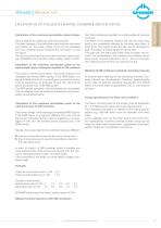
Calculation of the maximum permissible output voltage Various signals are added up within the combiner. The peak voltages of the individual signal must be calculated and added up. The peak voltage must not be calculated from the combined power because this will result in a too low gure. This sum must be less than the noted maximum output voltage. SPINNER recommends to keep a safety margin of 20%. Only CIB combiners are suitable to combine adjacent channels or blocks. The slope of the adjacent channel fed into the wide band input is not completely reected by the band pass lters. A small part of...
Open the catalog to page 5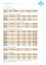
SPINNER || BROADCAST BAND 3 COMBINERS BAND 3 STRETCH LINE COMBINERS Part number Channel spacing Mask ltering BAND 3 CIB COMBINERS WITHOUT MASK FILTERING Part number Channel spacing Mask ltering BAND 3 DAB STARPOINT COMBINERS (1.54 MHZ BLOCK WIDTH) Part number Block spacing Mask ltering BAND 3 DAB CIB COMBINERS (1.54 MHZ BLOCK WIDTH) Part number Block spacing Mask ltering DAB or T-DMB DAB or T-DMB DAB or T-DMB DAB or T-DMB DAB or T-DMB DAB or T-DMB BAND 3 DTV STARPOINT COMBINERS Part number Block spacing Mask ltering BAND 3 DTV CIB COMBINERS Part number Mask ltering Block spacing Attention: The...
Open the catalog to page 6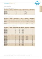
UHF STRETCH LINE COMBINERS Part number Channel spacing Mask ltering Multi Channel Combiners UHF STARPOINT COMBINERS Part number Channel spacing Mask ltering UHF MANIFOLD LOW POWER COMBINERS Part number Channel spacing Mask ltering Attention: The power at the Wide Band input must be reduced by 50 % of the power fed into the Narrow Band input Attention: The output power must not be exceeded Data subject to change without notice – Edition E
Open the catalog to page 7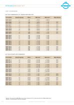
SPINNER || BROADCAST UHF COMBINERS UHF CIB COMBINERS IN 19" DESIGN AND MINI CCS Part number Channel spacing Mask ltering Mask ltering UHF HIGH POWER CIB COMBINERS Part number ATSC ATSC Channel spacing Attention: The power at the Wide Band input must be reduced by 50 % of the power fed into the Narrow Band input Attention: The output power must not be exceeded Data subject to change without notice – Edition E
Open the catalog to page 8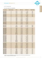
UHF HIGH POWER CIB COMBINERS Part number Channel spacing ATSC ATSC ATSC Mask ltering Multi Channel Combiners Attention: The power at the Wide Band input must be reduced by 50 % of the power fed into the Narrow Band input Attention: The output power must not be exceeded Data subject to change without notice – Edition E
Open the catalog to page 9
SPINNER || BROADCAST CHANNEL COMBINERS antenna Multi channel combiners In order to broadcast more transmitters via a common antenna it is necessary to connect the transmitter outputs via a combiner in such a way that they do not interfere (isolation) and to guide the whole RF power to the antenna (insertion loss). Band pass lters or phase adjusted transmission lines are used in the combiners as frequency determining devices. The band pass lters can additionally be used to suppress spurious emissions (integrated mask ltering for DTV, DAB, T-DMB, ...). multi channel combiner Starpoint or manifold...
Open the catalog to page 10
Stretch line combiners The difference in wave length of the transmitter frequencies is used with the stretch line combiner. The signals are split by the rst 3 dB coupler to two transmission lines. The phases at the input of the second 3 dB coupler are modied by careful adjustment of the line lengths in such a way that all signals are routed to the antenna output. The stretch line combiner has very low insertion loss and high power rating but can combine only channels with more than 3 channels spacing. balance load CHANNEL COMBINERS Multi Channel Combiners input 2 output to antenna Combination...
Open the catalog to page 11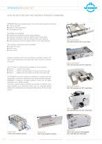
SPINNER || BROADCAST SOLUTIONS FOR LOW AND MEDIUM POWER COMBINERS SPINNER offers a complete range of low and medium power combiners: 1 W up to 5 kW Band 3, UHF and Band L ATV, DAB and DTV All designs are available: stretch line combiners without mask ltering starpoint combiners made of DAB and DTV mask lters manifold combiners with and without DTV mask ltering CIB combiners with and without DAB or DTV mask ltering BN 57 46 05 C0001 UHF CIB combiner with 4 cavity lters The compact combiners can be installed: inside 19" racks wall mount oor mount Multiple combiner units can be stacked vertically...
Open the catalog to page 12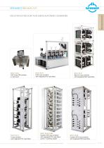
BN 57 45 90 UHF 4-way CIB combiner in wall mount BN 57 52 72 5-way combiner with integrated DTV mask lters BN 57 48 78 UHF 6-way combiner with integrated DTV mask lters BN 57 56 23 C1000 Double UHF 6-way combiner with integrated DTV mask lters and N+1 switching system Data subject to change without notice – Edition E SOLUTIONS FOR LOW AND MEDIUM POWER COMBINERS Multi Channel Combiners BN 57 54 81 Band 3 4-way combiner with integrated DAB mask lters BN 57 45 98 Double UHF 6-way combiner with integrated DVB mask lters
Open the catalog to page 13
SPINNER || BROADCAST SOLUTIONS FOR COMPACT COMBINING & SWITCHING SYSTEM 1 KW - 80 KW Modular system of combiners and patch panels to implement all functions with minimum foot print SPINNER has standardized and minimized the combiners and patch panels so much that a half square meter footprint per channel is sufcient to realize the combination, mask ltering and many switching functions. This design is called CCS and has many advantages: The combiner planning is very simple because only 0.5 m2 are sufcient per channel. The DTV mask ltering (uncritical or critical) can be integrated into the CCS...
Open the catalog to page 14All Spinner catalogs and technical brochures
 GSM-R Components
4 Pages
 Easy-Dock Push-Pull Adapter
4 Pages
 EasyDock Articulated Lines
4 Pages
 Space Systems Rotary Joints
4 Pages
 Fiber Optic Rotary Joints
12 Pages
 Radar Article
91 Pages
 Radar & Satellite Edition B
122 Pages
 ATC Rotary Joints Edition A
38 Pages
 Coaxial Switches Edition D
24 Pages
 Mobile Communication
202 Pages
 TETRA COMPONENTS
4 Pages
 MultiFit?
8 Pages
 Jumper Cables
4 Pages
 Rotary Joints
96 Pages
 Broadcast Components and Systems
160 Pages
 Components for Mobile Communication
168 Pages
 Surge Protectors
32 Pages
 Coaxial Switches
24 Pages
 Connector Catalogue
92 Pages


- Electrical rotary joint
- Circular connector
- Screw-in connector
- Socket electrical connector
- Technology switch
- Multipole switch
- Straight connector
- RF connector
- Electronic filter
- Electromechanical switch
- Screw connector
- DIN connector
- Right-angle electrical connector
- Coaxial connector
- Passive electronic filter
- IP68 connector
- Low-pass electronic filter
- Touch switch
- Combined connector