- Catalogs
- SPIETH-MASCHINENELEMENTE GmbH & Co KG
- Precision Shaft-Hub-Connection DSK - DSL
Precision Shaft-Hub-Connection DSK - DSL

Precision Shaft-Hub-Connection DSK - DSL
Catalog excerpts

Series DSK DSL Shaft-Hub-Connectionsfor tolerance fields h5/h6 Works Standard SN 01.01 >
Open the catalog to page 1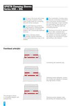
The combination of simply manu-factured connecting componentsand a low-priced clamping sleeve with the advantage of easy assembly and dismantling, make this an out- standing cost-effective shaft-hub connecting element.The amount of work for dismant-ling is often underestimated. If demands for a machine service or the question of recycling capability are present, the importance of quick dismantling is fully realized. To cope in the future with increa-sing levels of dynamic stress,higher quality shaft-hub connecting elements will be necessary.To avoid balancing problems,high-frequency rotating...
Open the catalog to page 2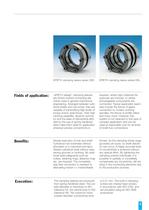
SPIETH designē clamping sleevesare friction-locked connecting ele- ments used in general mechanical engineering. Arranged between cylin- drical shafts and hub bores, they are capable of transmitting high levels of torque and/or axial forces. Their high centring capability, dynamic symme- try and the ease of dismantling affor- ded by the use of spring hardened steel make them ideal for application wherever precise concentricity is required, where high rotational fre-quencies are involved, or where exchangeable components are connected. Typical application exam- ples include the fixture of gears,...
Open the catalog to page 3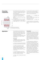
The cylindrical bore and outside sur-faces of the clamping sleeve must be completely covered by the connec- ting components. The manufacturing tolerance of the hub bore is H7 (H6 for stringent concentricity requirements, e.g. in gears). Manufacturing tolerance of the shaft: h5 (max. h6). The shaft and bore must be cylindri- cally machined with a mean peak-to- valley height of Rz = 2.5-6.3 microns. To ensure that the stress exerted onthe hub remains within the elastic range, we recommend the following minimum hub wall thickness:C 45 steel= 0,6 (d > 2 d > 1 )Aluminium alloysMinimum strength F38=...
Open the catalog to page 4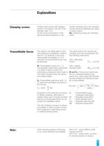
Cheese head screws with hexagon socket in compliance with ISO 4762, strength class 12.9. As the power transmission of the clamping sleeves depends on the exerted clamping force, the clampingscrews should be tightened by using a torque wrench. > A : Tightening torque per clampingscrew > The values in the table apply to follo-wing tolerance constellation: shaft h5,bore H7. For shaft h6, in the mostunfavourable constellation a 10 % reduction of transmittable forces may be expected. This phenomenon can hamper dis- mantling, and can be prevented with the following instructions:Adm. alternatingtorsion...
Open the catalog to page 5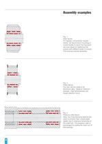
Fig. 1: Gear fixture. For highest concentricity require- ments, we recommend mounting a control facility to proof the concentri- city and adjust by tightening the screws with different levels of torque. This ensures precise assembly. Fig. 2: Pulley fixture. The hub can be made of an aluminium alloy. Observe minimumstrength. High temperatures can impair retention force! Fig. 3: Pressure roller fixture. Here, two long clamping sleeves areused to achieve high overall radial rigidity due to intensive tensioning of the shaft hub. The pressure roller is exchanged by pulling the shaft out of the bearings....
Open the catalog to page 8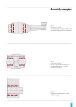
Fig. 4: Rocker arm fixture. The peripheral and axial position can be ideally adjusted during assembly. Fig. 5: Jaw clutch fixture. No grooves, shaft shoulders etc. A reasonably priced but highly effective connection. Fig. 6: Fixture of a guide column in the machine body. >
Open the catalog to page 9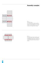
Fig. 7: Flywheel fixture. On a high-speed rotating working spindle, the arrangement of the pre- cisely concentric flywheel can help reduce the installed drive output. Fig. 8: Two shafts with rigid coupling using clamping sleeves. Due to possible overdefinition, attention must be paid to the admissible rotating bending stress. 10 >
Open the catalog to page 10All SPIETH-MASCHINENELEMENTE GmbH & Co KG catalogs and technical brochures
 catalogue
98 Pages
 Application documentation
20 Pages
 Clamping Nuts
8 Pages
 Radial Plain Bearings
6 Pages
 Guide Gibs
8 Pages
 Guide Bushings
16 Pages
 Clamping Sets
22 Pages
 Locknut
22 Pages
 Introduction
11 Pages
Archived catalogs
 Product Range
8 Pages
 Tension Nut Type AM
8 Pages
 Precision Locknut heavy MSW
12 Pages
 Precision Locknut MSR/MSA
12 Pages


