- Catalogs
- SPIETH-MASCHINENELEMENTE GmbH & Co KG
- Precision Shaft-Hub-Connection AK - IL
Precision Shaft-Hub-Connection AK - IL

Precision Shaft-Hub-Connection AK - IL
Catalog excerpts

Series AKAL und IK֖IL Friction-locked connections Works Standard SN 01.05 >
Open the catalog to page 1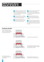
The type of clamping force initia-tion (mechanical, hydraulic,pneumatic) can be configured indivi- dually by the designer in line with the specifications.Simple assembly and, mostimportant, easy dismantling are a matter of course using clamping sleeves.The ease of dismantling affordedby clamping sleeves permits sim-ple compliance with today's machine and plant service and recycling requi- rements. Connecting components used inmechanical engineering are sub-jected to increasing levels of dynamicstress, requiring the use of high quali-ty machine elements.Precise centring of connectedcomponents...
Open the catalog to page 2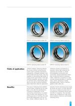
SPIETH designē clamping sleevesare friction-locked connecting ele- ments used in general mechanical engineering. Arranged between cylin- drical shafts and hub bores, they are capable of transmitting high levels of torque and/or axial forces. Their high centring capability, dynamic symme- try and the ease of dismantling affor- ded by the use of spring hardened steel make them ideal for applicationThe type of clamping force initiationcan be freely configured by the desi-gner in line with the specifications. Cylindrical configuration of the connecting components, no weake- ning of shaft cross-sections...
Open the catalog to page 3
The clamping sleeves are producedfrom spring-hardened steel. The out-side diameter is machined to ISO tolerance h5, the central bore to ISOtolerance H6. The maximum bore/outside diameter /end face concentricity error is 0.01mm.Two different series (AK/AL and IK/IL)are offered to enable the different types of clamping force initiation. The AK/AL series sleeves are desi- gned for use where the clamping force is initiated from the housing(Page 5, Fig.1). IK/ILseries clamping sleeves are usedin cases where clamping force is ini- tiated from the shaft (Page 5, Fig. 2). However, of decisive importance...
Open the catalog to page 4
The cylindrical bore and outside sur-faces of the clamping sleeve must becompletely covered by the connec- ting components. To permit simple configuration of the connecting components, however, projection of the clamping sleeve up to max. a (Fig. 1 and 2) can be tole- rated.The manufacturing tolerance of thehousing bore is H7; with high dyna- mic stress, for example in the case of a hydraulic actuated clamp, H6.Manufacturing tolerance of the shaft: h5 (max. h6). The shaft and bore must be machi-nedcylindrically with a mean peak-to- valley height of Rz = 2.5-6.3 microns. The end face contact surfaces...
Open the catalog to page 5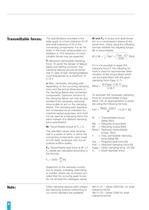
The specifications provided in thetable apply to a bore tolerance of H7 and shaft tolerance of h5 in the connecting components. For an h6shaft, in the most unfavourable con- stellation a 10% reduction of trans- mittable forces may be expected. F: Maximum permissible clampingforce. To avoid the danger of fatigue failure and fretting corrosion, theclamping sleeves should be tensio-ned in case of high clamping/release cycle frequencies to a maximum of 0.75 F. M und F > a : If torque and axial forcesact on a compression sleeve at the same time, check using the followingformula whether the resulting...
Open the catalog to page 8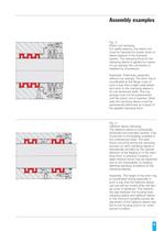
Fig. 3: Piston rod clamping. For safety reasons, the piston rod must be clamped for power down or failure reasons of the hydraulic system. The clamping force for the clamping sleeve is applied by means of cup springs; the connection is released by oil pressure.Assembly: Preliminary assemblywithout cup springs. The shim ring is coordinated at the flange cover in such a way that a slight axial preten- sion acts on the clamping sleeve in its non-tensioned state. The cup springs must not be pretensioned until the piston rod is inserted. Other- wise the clamping sleeve could be permanently deformed...
Open the catalog to page 9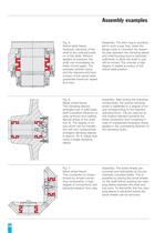
Assembly: The shim ring is coordina-ted in such a way that, when the flange cover is mounted, the assem- bly play between the clamping sleeve and shaft/housing bore is restricted sufficiently to allow the shaft to just still be turned. This ensures a high degree of repeat accuracy of the swivel table position. Assembly: After joining the individualcomponents, the central clamping screw is tightened to a degree of tor- que corresponding to the required clamping force. The pin used as an anti-rotation element prevents the entire connection from loosening in case of unexpected excessive stress applied...
Open the catalog to page 10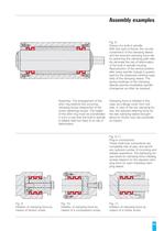
Fig. 8: Fixture of a built-in spindle. With this type of fixture, the circular constriction of the clamping sleeve and the reduced clamping force set by restricting the clamping path relia- bly eliminate the risk of deformation of the built-in spindle housing. Reproduction of the central position after every spindle change is guaran- teed by the advanced centring capa- bility of the clamping sleeve. The spring hardness of the clamping sleeves permits troublefree spindle changeover as often as required.Assembly: The arrangement of theshim ring restricts the occurring clamping forces irrespective...
Open the catalog to page 11All SPIETH-MASCHINENELEMENTE GmbH & Co KG catalogs and technical brochures
 catalogue
98 Pages
 Application documentation
20 Pages
 Clamping Nuts
8 Pages
 Radial Plain Bearings
6 Pages
 Guide Gibs
8 Pages
 Guide Bushings
16 Pages
 Clamping Sets
22 Pages
 Locknut
22 Pages
 Introduction
11 Pages
Archived catalogs
 Product Range
8 Pages
 Tension Nut Type AM
8 Pages
 Precision Locknut heavy MSW
12 Pages
 Precision Locknut MSR/MSA
12 Pages


