Catalog excerpts
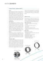
SPIETH LOCKNUTS 4 UNIQUE FEATURES - NUMEROUS BENEFITS The locking system enables the application of high clamping forces to ensure that the nut is friction-locked onto the spindle thread. The load is applied to the thread across 3600 sym- metrically and evenly. The locking force and working load act in the same direction and cannot cancel each other out. This is the re- quirement for the highest locking effect while at the same time preserving the connecting The locking procedure is designed to exert a self-centring effect for the nut on the spindle thread. This is the prerequisite for...
Open the catalog to page 3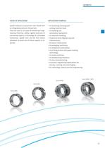
Spieth locknuts are precision nuts fitted with an integrated premium thread lock. They are used in all areas of mechanical engi- neering. Precision, safety, rigidity and ease of use are key aspects in the design of a threaded connection. Spieth nuts are the first choice whenever at least one of these aspects is re- APPLICATION EXAMPLES cutting machine tools. automation equipment. • In general drive engineering and • In printing presses and paper-making • In process engineering applications for mixing, crushing and centrifuging. • For metrology, control and test engineering.
Open the catalog to page 4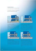
FUNCTIONAL PRINCIPLE In this example, based on a type MSF locknut. The principle is illustrated in a simplified dia- gram with enlarged thread flank play. As with every threaded connection, there is a degree of mating play when the nuts are screwed on. As a result, the nut may be aligned with a parallel and/or angled axial offset rela- tive to the spindle axis; in other words, the 2. Spieth locknuts: Self-centring and self- aligning thanks to play restriction Unique: Spieth locknuts are automatically self-centring and eliminate mating play (thread flank play) as far as possible. Thanks to...
Open the catalog to page 5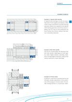
ASSEMBLY EXAMPLES Example 1: Tapered roller bearing In tapered roller bearings, run-out accuracy, a high level of axial rigidity and dynamic safety create a major contribution to perfect bearing operation: Radial stress applied to the tapered roller bearing generates axial forces (axial ri- gidity). Due to a lack of axial pretension (no axial friction), the intrinsic safety of the lock- Example 2: Ball roller spindle The use of a locknut gives the bearing of the ball roller spindle a high degree of axial rigid- ity. Under highly dynamic operating condi- tions, the high degree of dynamic...
Open the catalog to page 6
ASSEMBLY EXAMPLES Example 4: Main spindle bearing The locknut ensures a high level of axial rigid- ity and excellent concentricity on the main spindle bearing in a turning lathe. Example 5: Round axis Not a millimetre is lost in the axial direction and, despite this, there is no need to sacrifice run-out accuracy, axial rigidity or a high de- gree of dynamic safety. Example 6: Table structure Due to the flat design, countersunk installa- tion is possible without causing any interfer- ing contours in the table surface. Straining of the structure due to a tilting locknut caused by thread...
Open the catalog to page 7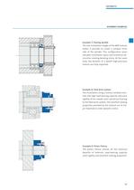
ASSEMBLY EXAMPLES Example 7: Tooling spindle The low installation height of the MSF locknut makes it possible to create a compact drive side of the spindle. This configuration saves valuable installation space and minimises de- structive rotating bending stress. At the same time, the benefits of a Spieth high-precision locknut are fully exploited. Example 8: Feed drive system The installation using a locknut reliably trans- mits the high load-bearing capacity and axial rigidity of the needle axial cylindrical bearing to the feed drive system. The excellent locking properties provided by the...
Open the catalog to page 8
SPIETH LOCKNUTS: THE RIGHT CHOICE We'll provide you with the perfect locknuts for your application. We'll also help you choose the right one - with expert advice from our Series AASR - MSA, AASF and MSW • Excellent axial rigidity and loading capacity under high levels of dynamic stress. • Simple connecting components, no grooves, • Axial position of the contact surface can be easily and precisely adjusted. • Even in the installed state, exact run-out accuracy, which can be further improved with adjustment. Reduced contact cases with reduced outer diameter
Open the catalog to page 10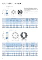
SPIETH LOCKNUTS SERIES MSR The admissible operating loads specified in the table are guideline values calculated with • under static stress relative to the minimum yield point, • under dynamic stress relative to the mini- Clamping screws Calcu- Calcula- Perm, axial Moment lation tion stress of No. factor factor | inertia
Open the catalog to page 11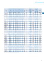
11 The number of holes corresponds to the number of clamping screws.
Open the catalog to page 12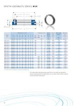
SPIETH LOCKNUTS SERIES MSR 1!The number of holes corresponds to the number of clamping screws. The admissible operating loads specified in the table are guideline values calculated with a safety factor of 1.6 under static stress relative to the minimum yield point.
Open the catalog to page 13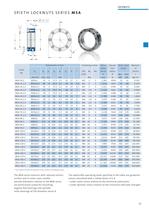
SPIETH LOCKNUTS SERIES MSA 11 The number of holes cor res ponds to the number of clamping screws. The MSA series locknuts with reduced contact surface and in some cases smaller outside diameters relative to the MSR series are particularly suited for mounting angular ball bearings and cylinder roller bearings of ISO diameter series 9. The admissible operating loads specified in the table are guideline values calculated with a safety factor of 1.6 • under static stress relative to the minimum yield point, • under dynamic stress relative to the minimum alternate strength.
Open the catalog to page 14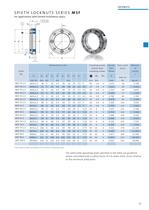
SPIETH LOCKNUTS SERIES MSF For applications with limited installation space. Clamping screws cheese head clamping screws 11 The number of holes cor res ponds to the number of clamping screws. The admissible operating loads specified in the table are guideline values calculated with a safety factor of 1.6 under static stress relative to the minimum yield point.
Open the catalog to page 16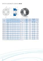
SPIETH LOCKNUTS SERIES MSW 11 The number of grooves for hook spanner DIN 1810-A corresponds to the number of clamping screws. Perm, axial
Open the catalog to page 17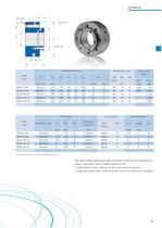
Lock screws 21 Manufacturer's max. permissible tightening torque. The admissible operating loads specified in the table are guideline values calculated with a safety factor of 1.6 • under static stress relative to the minimum yield point, • under dynamic stress relative to the minimum alternate strength.
Open the catalog to page 18All SPIETH-MASCHINENELEMENTE GmbH & Co KG catalogs and technical brochures
-
catalogue
98 Pages
-
Application documentation
20 Pages
-
Clamping Nuts
8 Pages
-
Radial Plain Bearings
6 Pages
-
Guide Gibs
8 Pages
-
Guide Bushings
16 Pages
-
Clamping Sets
22 Pages
-
Introduction
11 Pages
Archived catalogs
-
Product Range
8 Pages
-
Tension Nut Type AM
8 Pages
-
Precision Locknut heavy MSW
12 Pages
-
Precision Locknut MSR/MSA
12 Pages


