- Catalogs
- SPIETH-MASCHINENELEMENTE GmbH & Co KG
- Clamping Sets
Clamping Sets
1 /22Pages

Clamping Sets
1 /22Pages
Catalog excerpts

G ALL-ROUND PRESSURE WITH PRECISION pieth clamping sets - friction-locked shaft- sing power densities. Increasing levels of dynamic :ress. And the required function must be realised 'ithin increasingly restrictive cost parameters. ne stringent demands of modern mechanical en- neering can only be satisfied with high-quality naft-hub connecting elements. Dieth clamping sets apply uniform pressure. With- ut compromise. The are designed to be more ac- jrate, precise, efficient, simpler to install and eas- r to service. The economical solution for modern lachinery designs. Offering outstanding perform-
Open the catalog to page 1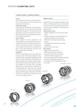
SPIETH CLAMPING SETS 4 UNIQUE FEATURES - NUMEROUS BENEFITS All functional surfaces that determine preci- sion are machined to the finest geometrical Single-piece design Unlike tapered clamping sets, the single-piece steel body does not have any joints that could compromise tolerances. This ensures that the high degree of precision achieved in the man- ufacturing process can also be brought to bear When subjected to axial compression, the unique geometry of the absolutely symmetri- cal base body ensures uniform transverse con- traction in the direction of the shaft and hub. The resulting centring...
Open the catalog to page 3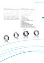
CLAMPING SETS Spieth clamping sets are friction-locked shaft- hub connections for all areas of mechanical engineering. They are used wherever high- quality and reliable connections perform key functional roles. At the same time, they are the ideal solution for applications with high levels of replacement and adjustment as well as for manual or automated clamping of sleeves, skids, pivoting heads or rotary tables. APPLICATION EXAMPLES • In machining, forming and cutting machine • In handling and automation equipment. • In general drive engineering and • In printing presses and paper-making • In...
Open the catalog to page 4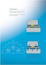
FUNCTIONAL PRINCIPLE Shown here using a clamping set from series DSK with an integrated clamping screw. The principle is illustrated in a simplified dia- gram with enlarged play. Clamping set re leased, easy in stall at ion or dis- mantling with mating play. Clamping set clamped, connection is centred with a high load capacity. No lateral displace- ment during tightening. This ensures ultra- high precision centring and optimum concen-
Open the catalog to page 5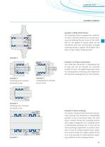
ASSEMBLY EXAMPLES Example 1: Blade wheel fixture The clamping sleeves arranged over a wide ba- sis exert a positive influence on run-out accu- racy and rotating flexural stress of the shaft- hub fit. The degree of torque which can be transferred with two consecutively arranged clamping sleeves is approx. 30 % higher than when using a single clamping sleeve. Clamping force initiated Clamping force initiated Example 2-4: Plug-in connections This shaft-hub connection is completely free of play and can be released an unlimited number of times. The tightening torque levels for clamping force initiating...
Open the catalog to page 6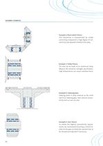
Example 6: Bevel wheel fixture This connection is characterized by simple connecting components, a high degree of con- centricity and absolute freedom from play. Example 7: Pulley fixture The hub can be made of an aluminium alloy. Observe the minimum strength specification. High temperatures can impair retention force. Example 8: Indexing plate Indexing plate in alloy material at the shaft end of an indexing gear. Here, precise concen- tricity and run-out are vital. Example 9: Gear fixture To satisfy the highest concentricity require- ments, we recommend mounting a control fa- cility on the gear...
Open the catalog to page 7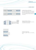
CLAMPING SETS ASSEMBLY EXAMPLES Example 10: Pressure roller fixture Here, 2 long clamping sets are used to achieve high overall radial rigidity due to intensive tensioning of the shaft and hub. The pressure roller is exchanged by pulling the shaft out of Example 11: Rocker arm fixture The peripheral and axial position can be ide- ally adjusted during assembly. Example 12: Guide column Fixture of a guide column in the machine
Open the catalog to page 8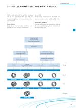
CLAMPING SETS SPIETH CLAMPING SETS: THE RIGHT CHOICE We'll provide you with the perfect clamping sets for your application. We'll also help you choosetheright one-wit h expert advice from Ready-to-use friction-locked shaft-hub con- nection for quick and easy installation. Ready-to-use friction-locked shaft-hub con- nection for use on motor shafts to DIN 748. Series AK/IK and AL/IL Friction-locked shaft-hub connection that can be automated. Clamping force initiation can
Open the catalog to page 10
SPIETH CLAMPING SETS SERIES DSK For shafts with h tolerance zone Clamping screws
Open the catalog to page 11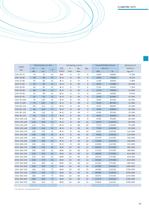
CLAMPING SETS Transmittable forces
Open the catalog to page 12
SPIETH CLAMPING SETS SERIES DSL For shafts with h tolerance zone
Open the catalog to page 13
CLAMPING SETS
Open the catalog to page 14
SPIETH CLAMPING SETS SERIES DSM For motor shafts to DIN 748 with k6/m6 tolerance zone
Open the catalog to page 15
Transmittable forces
Open the catalog to page 16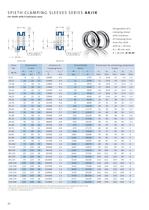
SPIETH CLAMPING SLEEVES SERIES AK/IK For shafts with h tolerance zone clamping force clamping sleeve with initiation Dimensions for connecting components 11 Max. perm, clamping force. For automated operation, the clamping sleeve should be clamped with max. 21 Design specification, not to be confused with actuation travel. For explanations, see p. 55.
Open the catalog to page 17
CLAMPING SETS SPIETH CLAMPING SLEEVES SERIES AL/IL For shafts with h tolerance zone clamping sleeve clamping force clamping force 11 Max. perm, clamping force. For automated operation, the clamping sleeve should be clamped with max. 0.75xF. 21 Design specification, not to be confused with actuation travel. For explanations, see p. 55.
Open the catalog to page 18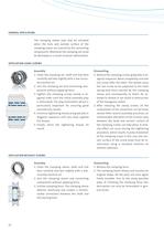
GENERAL APPLICATION The clamping sleeve may only be actuated when the bore and outside surface of the clamping sleeve are covered by the connecting components. Otherwise the clamping set could be destroyed as a result of plastic deformation. APPLICATION USING SCREWS 1. Clean the clamping set, shaft and hub bore carefully and wet slightly with a low-viscos- 2. Join the clamping set and connecting com- ponents without applying force. 3. Tighten the clamping screws evenly in di- agonal order until the initial assembly play is eliminated. The play elimination phase is particularly important for ensuring...
Open the catalog to page 19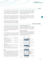
CLAMPING SETS The clamping sets are manufactured from spring-hardened steel. The concentricity of the bore/outside diameter is accurate to 0.008 mm The outside diameter is machined according to inside diameter is machined to ISO tolerance for use where the clamping force is initiated from the housing (Fig. 1). IK/IL series clamping sleeves are used in cases where clamping force is initiated from the shaft (Fig. 2). However, of decisive importance is that the clamping force is applied to the end faces of the clamping sleeves in the area of diameter Two different series (AK/AL and IK/IL) are offered...
Open the catalog to page 20All SPIETH-MASCHINENELEMENTE GmbH & Co KG catalogs and technical brochures
 catalogue
98 Pages
 Application documentation
20 Pages
 Clamping Nuts
8 Pages
 Radial Plain Bearings
6 Pages
 Guide Gibs
8 Pages
 Guide Bushings
16 Pages
 Locknut
22 Pages
 Introduction
11 Pages
Archived catalogs
 Product Range
8 Pages
 Tension Nut Type AM
8 Pages
 Precision Locknut heavy MSW
12 Pages
 Precision Locknut MSR/MSA
12 Pages


