- Catalogs
- SPIETH-MASCHINENELEMENTE GmbH & Co KG
- Adjustable Round Guiding and Clamping Elements
Adjustable Round Guiding and Clamping Elements

Adjustable Round Guiding and Clamping Elements
Catalog excerpts

Round guiding and clamping elements with adjustable play Works standard SN 02.04 >
Open the catalog to page 1
Provides the typical high dam-ping performance characteristicfor slideways.Optimum guide play adjustmentpossible for any operating status.Precisely central play restrictionand clamping of the sleeve orcolumn. Low-cost, ready-to-mount guideand clamping bushing.Existing assembling play ensures simple mounting even with largedimensions.Metallic support between clam-ped sleeve and housing affordshigh radial rigidity. > Mounting situation Connection with assembling play between the housing, guide bushing and centre sleeve. Play adjusted Firm fit of the guide bushing in the housing, the guide play...
Open the catalog to page 2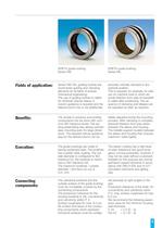
Fields of application: > Series FAK-FAL guiding bushes areround linear guiding and clamping elements for all fields of precise mechanical engineering. The use of guiding bushes is called for wherever precise sleeve or column guidance is required and the sleeve/column has to be additionallyprecisely centrally clamped in anyoptional position. This is required,for example,for slee- ves on machine tools in which ab- solute freedom from play at standstill is called after positioning. The se- quence of clamping and release can be repeated as often as required. Benefits: > The simple to produce surrounding...
Open the catalog to page 3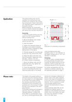
Assembly 1. Insert the guide bushing and ring piston into the housing borehole without exerting force.2. Mount the flange cover looselywithout the shim ring.3. Insert the sleeve. 4. Tighten the clamping screws atthe flange cover evenly crosswise until loss of play is indicated by stiffer sliding action of the sleeve. 5. Precisely gauge the mounting gapfor the shim ring, remove the cover.6. Adjust the high of the shim ring.Recommendation: Measured moun- ting gap + approx. 0.02 mm for contact surface compression. 7. Mount the flange cover and theunderneath shim ring, tighten thescrews crosswise.8....
Open the catalog to page 6All SPIETH-MASCHINENELEMENTE GmbH & Co KG catalogs and technical brochures
 catalogue
98 Pages
 Application documentation
20 Pages
 Clamping Nuts
8 Pages
 Radial Plain Bearings
6 Pages
 Guide Gibs
8 Pages
 Guide Bushings
16 Pages
 Clamping Sets
22 Pages
 Locknut
22 Pages
 Introduction
11 Pages
Archived catalogs
 Product Range
8 Pages
 Tension Nut Type AM
8 Pages
 Precision Locknut heavy MSW
12 Pages
 Precision Locknut MSR/MSA
12 Pages


