
- Catalogs
- Spencer Turbine Company
- FF single stage scroll blower

FF single stage scroll blower

FF single stage scroll blower
Before uncrating and installing the Spencer Scroll Blower, it is essential to familiarize yourself with the manual to ensure efficient service and longevity. Improper handling or installation can void the warranty, which covers defects for 18 months from shipment or 12 months from startup, excluding misuse or unauthorized alterations.
The machine is factory-tested and must be handled carefully during installation. If stored for long periods, it should be protected from dampness, dirt, and vibration. Inlets and discharge should be covered to prevent foreign matter entry, and the motor shaft should be periodically rotated.
The blower should be installed in a location that is not excessively hot and allows easy access for servicing. A level concrete floor is recommended, and the blower should be placed on cork isolating pads.
All tubing joints must be airtight to prevent power loss and inefficiency. Electrical equipment must comply with codes, and proper voltage and starting equipment are crucial.
Inlet air filters should be used to prevent pressure drop and maintain efficiency. Silencers should be properly supported and connected with a rubber sleeve.
After installation, check and realign the motor and blower shafts if necessary. Misalignment can cause vibration and damage. Use methods like laser alignment or the straightedge method for precise alignment.
Before starting the blower, ensure all installation steps are complete, and perform checks on adjustments and operational readiness. Avoid operating the blower in surge conditions to prevent mechanical failure.
Review installation and setup before first operation. Ensure the machine is level, all materials are removed, and all connections are secure. Check motor rotation and ensure all electrical accessories are properly wired.
Use a flange-type gear coupling for sleeve bearing motors. Align the motor with the blower using specified procedures, ensuring proper clearance and alignment.
Avoid operating the blower in surge conditions, which can cause excessive temperatures and mechanical failure. Increase airflow to eliminate surge.
Reassemble parts in their original positions. Tagging each part during disassembly is recommended, especially marking the impeller's location on the shaft to ensure proper balance and minimize vibration issues.
Machines are tested for vibrations before leaving the factory. If vibration occurs, adjust the impeller's position on the shaft by rotating it in 90-degree increments until balance is achieved.
Maintenance involves removing the motor and end head to access the impeller. Mark the impeller's position, loosen screws, and remove the impeller. Remove the motor for overhaul, replacing division head packing as needed.
Reinstall the motor, ensuring proper alignment and that the fan turns freely. Secure all components and check motor connections and rotation direction.
Ensure correct blower rotation direction. Connect the blower to the pipe system before operation. Use an ammeter to adjust the control device to prevent overloading.
Operate all blowers periodically and install check valves to prevent blow-back. Ensure each blower shares the load by setting blast gates within motor load ratings.
Disconnect power before lubrication. Follow motor manufacturer guidelines. Blower bearings are pre-greased for 1500-8000 hours. Adjust lubrication intervals based on operating conditions.
Provide complete information when ordering parts to avoid delays. Include machine model, serial number, motor horsepower, and casing diameter.
Common issues include insufficient air, noise, vibration, and overheating. Solutions involve checking rotation, adjusting system components, cleaning, and ensuring proper motor operation.
Standard features include flanged outlets and heavy-duty construction. Optional features offer customization for specific applications, such as special materials, coatings, and motor enclosures.
The document outlines the specifications of a radial bladed aluminum impeller used in blowers, highlighting maximum vibration tolerance and balancing before shipment. The design ensures high efficiency and lower sound levels, with flexible outlet positions and standard motor enclosures.
If the impeller is damaged due to sudden back pressure, sections can be repaired or replaced. Refer to Spencer Bulletin No. TDS192 for detailed specifications on Single-stage Scroll Blowers.
The Spencer Turbine Company offers a range of industrially rated products for air and gas handling, including various types of blowers and modular central vacuum systems. They also provide custom-engineered products and complementary accessories.
The company provides comprehensive engineering support, including technical specialists, worldwide parts and service, application research, and testing facilities. They offer product selection, installation, operation assistance, system design services, and troubleshooting through a global network of sales representatives and distributors.
Catalog excerpts
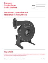
Spencer® Single-Stage Scroll Blowers Installation, Operation and Maintenance Instructions Important Read and become familiar with this manual prior to uncrating and installing your Spencer Scroll Blower. Following the instructions detailed here will help you realize its full potential of efficient service and extended lifespan. Damage resulting from failure to follow correct procedure will void the warranty. The Spencer Turbine Company
Open the catalog to page 1
Before proceeding with this set-up, refer to the machine nameplate and record the machine number and serial number in the boxes on the manual front cover. I. General Instructions Important Read and become familiar with this manual prior to uncrating and installing or storing machinery – it is a precision piece of equipment capable of extended service and lifespan. Realization of this potential can best be achieved through proper handling and adherence to the following instructions. Damage resulting from failure to follow correct procedures will void warranty. Spencer Service Spencer service begins...
Open the catalog to page 2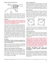
Rubber Inlet and Outlet Sleeve The rubber connecting sleeve supplied with the scroll should be installed so that it covers a gap of approximately one inch as illustrated. The mounting clamps supplied with the sleeve should be adequately tightened to effect an air-tight connection. Vacuum Applications When the machine is used for vacuum, the outlet should discharge outdoors (preferred) or into a room having ample volume and proper ventilation in order to permit the air to escape and at the same time keep the unit at a reasonable temperature. Intake air must be kept clean through proper filtration...
Open the catalog to page 3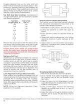
Coupling alignment lines up the motor shaft and blower shaft in horizontal and vertical planes. It also ensures an adequate clearance (gap) between the two coupling halves. Only qualified personnel should attempt to align a coupling. If problems arise, contact Spencer or your Spencer Representative. Sier Bath Gear-Type Couplings, manufactured to our rigid specifications, are most commonly supplied with Spencer equipment. Remove one snap ring and slide the sleeve off the hub halves. Using a feeler gage, verify that the gap between the coupling halves agrees with this table. Reverse Indicator Method...
Open the catalog to page 4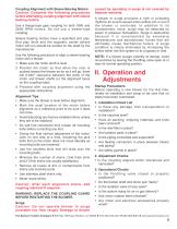
Coupling Alignment with Sleeve Bearing Motors Caution: Complete the following procedures before attempting coupling alignment with sleeve bearing motors. Use a flange-type gear coupling for both 1800 and 2600 RPM motors. Do not use a sleeve-type coupling. Sleeve bearing motors have a specified end play. End play limits and the magnetic center (where motor will run) should be scribed on the shaft by the manufacturer. Use the following procedure to align a sleeve bearing motor with a blower. 1. Make sure the motor shaft is level. 2. Position the motor so that when the rotor is pushed toward the...
Open the catalog to page 5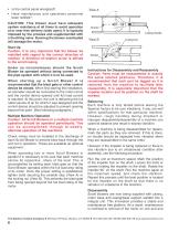
• Is the control panel energized? • Have maintenance and operations personnel been notified? CAUTION: This blower must have adequate system resistance at all times to avoid operation at or near free delivery (wide open). It Is typically imposed by the process and supplemented with a throttling valve. Running the blower overloaded will damage the motor. Start Up Caution: It is very important that the blower be installed with regard to the correct direction of rotation. A direction-of-rotation arrow is affixed to the scroll casing. Under no circumstances should the Scroll Blower be operated without...
Open the catalog to page 6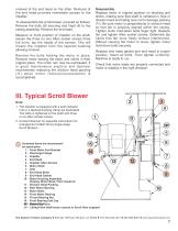
removal of the end head on the other. Removal of the end head provides immediate access to the impeller. To disassemble the scroll blower, proceed as follows: Remove the bolts (8) securing end head (4) to the casing assembly. Remove the end head. Measure or mark position of impeller on the shaft, loosen the three (or six) Allen socket screws three full turns, tap the heads of the screws. This will loosen the impeller from the tapered bushing allowing removal. Remove the bolts holding the motor in place. Remove motor leaving the block and shims in their original place. The motor can now be overhauled....
Open the catalog to page 7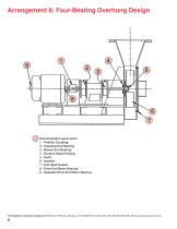
Arrangement 8: Four-Bearing Overhung Design 8 6 7 Recommended spare parts 1 - Flexible Coupling 2 - Coupling End Bearing 3 - Blower End Bearing 4 - Division Head Packing 5 - Shaft 6 - Impeller 7 - End Head Gasket 8 - Drive End Motor Bearing 9 - Opposite Drive End Motor Bearing The Spencer Turbine Company ◆ 600 Day Hill Road, Windsor, CT 06095 ◆ TEL 800-232-4321 ◆ 860-688-8361 ◆ www.spencerturbine.com
Open the catalog to page 8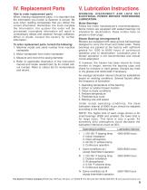
How to order replacement parts When ordering replacement parts, it is important that the information you furnish to Spencer is correct. Be sure when reading nameplates that you obtain the correct information. Remember, the more complete the information, the quicker the order will be processed; incomplete information will result in unnecessary delays and expense through callbacks. When in doubt, consult the factory for further information. WARNING: DISCONNECT AND LOCK OUT ELECTRICAL POWER BEFORE PERFORMING LUBRICATION. To order replacement parts, furnish the following: 1. Machine model and serial...
Open the catalog to page 9
VI. Trouble Shooting Guide Trouble Probable Cause Corrective Action Insufficient air Low pressure or vacuum as determined by measurement with a manometer: through system – Incorrect rotation. Change motor leads to correct rotation. – Machine sized for requirements given, but air lines too small Increase line sizes or install machine providing higher causing excessive frictional loss. output pressure. – Valves in line, causing excessive losses. Install larger valves or install machine providing higher output pressure. – Inlet or outlet partially blocked, i.e., clogged inlet filter, Check blast...
Open the catalog to page 10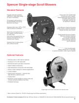
Spencer Single-stage Scroll Blowers Standard Features Flanged outlet with standard ANSI B16.5 125lb/150lb drilling for ease of installation. Heavy-duty 3⁄16" welded steel housing and motor support. Heavy-gauge steel absorbs shock of sudden back pressure. If damaged, sections can be repaired or replaced. Six standard outlet positions provide flexibility of air piping placement and layout. Standard shaft motor. ODP or TEFC motor enclosure is standard. High efficiency wheel and housing design results in optimum efficiency ratings and lower sound levels. Direct drive Arrangement No. 4, with impeller...
Open the catalog to page 11


