


5T series

5T series
- Dimensions are provided in millimeters (inches) unless otherwise stated.
- Thread sizes include M3, 4-40, M3.5, and 6-32 with corresponding part numbers and tool part numbers.
- Material and Finish: Screws are made of hardened carbon steel with zinc plating and chromate sealer. Springs are made of 300 series stainless steel, passivated. Ferrules are aluminum, natural finish.
- Recommended Torque: M3/4-40 at 0.6 N·m (5.3 in·lbf) and M3.5/6-32 at 1.08 N·m (9.6 in·lbf).
- Load applied by each screw is calculated as [3.4 (.13) * K] +7.57 N (1.7 lb).
- Drill and countersink according to specified dimensions.
- Insert screw assembly into the prepared hole in the panel and use a back-up tool.
- Place work under press, center tool over screw thread, and flare ferrule into countersink in panel. Recommended load is 2200 N.
- Maximizes heat transfer from components to heatsink.
- Provides positive fastening under shock and vibration.
- Allows for thermal expansion of components under a set preload.
- Standard K value is provided in the table.
- Load at given deflection is shown in the fastened position.
Catalog excerpts

5T Captive ScrewsHeat sink series • Maximize heat transfer from components to heatsink • Positive fastening under shock and vibration • Fastener allows for thermal expansion of components under a set preload Material and Finish Screw: Hardened carbon steel, zinc plate, chromate plus sealer Spring: 300 series stainless steel, passivated Ferrule: Aluminum, natural Performance Details M3/4-40 Recommended Torque: 0.6 N-m (5.3 in-lbf) M3.5/6-32 Recommended Torque: 1.08 N-m (9.6 in-lbf) Installation Notes 1. Drill then countersink according to the required dimensions. 2. Insert screw assembly into prepared hole in panel. Place back-up tool as shown. 3. Place work under press, center tool over screw thread and flare ferrule into countersink in panel. Recommended load 2200 N. Notes Load applied by each screw: [3.4 (.13) * K] +7.57 N (1.7 lb) Standard K value shown in the table. Load at given deflection *shown in the fastened position above. Part Number See table Unfastened Fastened Thread Size Thread Size Spring Rate K N/mm (lbf/in) Dimensions in millimeters (inch) unless otherwise stated southcor CONNECT • CREATE • INNOVATE
Open the catalog to page 1All SOUTHCO catalogs and technical brochures
 P9
P91 Page
 64
648 Pages
 A3
A34 Pages
 D1 - DZUS®
4 Pages
 C5
C52 Pages
 AV Series Dynamic Mount
4 Pages
 G6 Hinge
2 Pages
 R4 Rotary Latch
12 Pages
 R6 series
3 Pages
 47, 4C series
36 Pages
 52 series
7 Pages
 09, 1x series
9 Pages
 N7 series
2 Pages
 D7 - DZUS® series
4 Pages
 D3 - DZUS® series
25 Pages
 D1 - DZUS® series
5 Pages
 19, 84 series
5 Pages
 LG, LM series
6 Pages
 NY-N6
NY-N62 Pages
 B4 Handle
1 Page
 PT Tubular Key Cam Locks
2 Pages
 57 Compression Latch
6 Pages
 C5 Compression Latch
2 Pages
 A7 Compression Latch
2 Pages
 E3 Compression Latch
27 Pages
 LP - Cam Latches
1 Page


Archived catalogs
 E3
E331 Pages
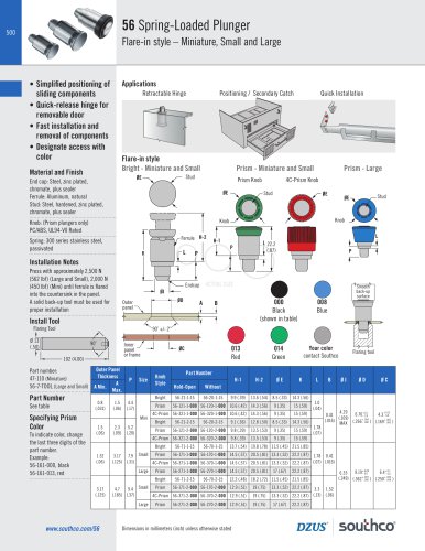 56 Spring Loaded Plunger
6 Pages
 MA
MA6 Pages
 09
099 Pages
 R4 Push-to-Close Latch
1 Page
 M1 Push-to-Close Latch
1 Page
 F6 series
4 Pages
 M5 series
1 Page
 5x series
11 Pages
 56 series
4 Pages
 NY - NYLATCH
2 Pages
 67 Concealed Pull
2 Pages
 GA - Gaskets
1 Page
 10/38 - Drive Rivets
3 Pages
 C2 Compression Latch
1 Page
 P1 Flush Pull
1 Page
 01 - Flush Cup Cam Latches
4 Pages
 HP - Cam Latches
1 Page
 E5 - Quad Panel Latches
14 Pages


